|
5. Work from the photos - not the diagrams! |
|
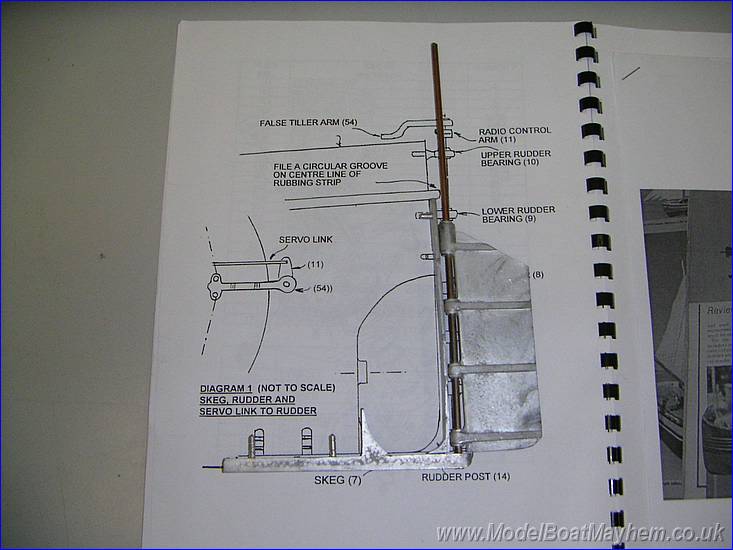 |
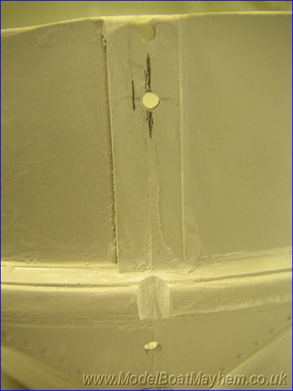
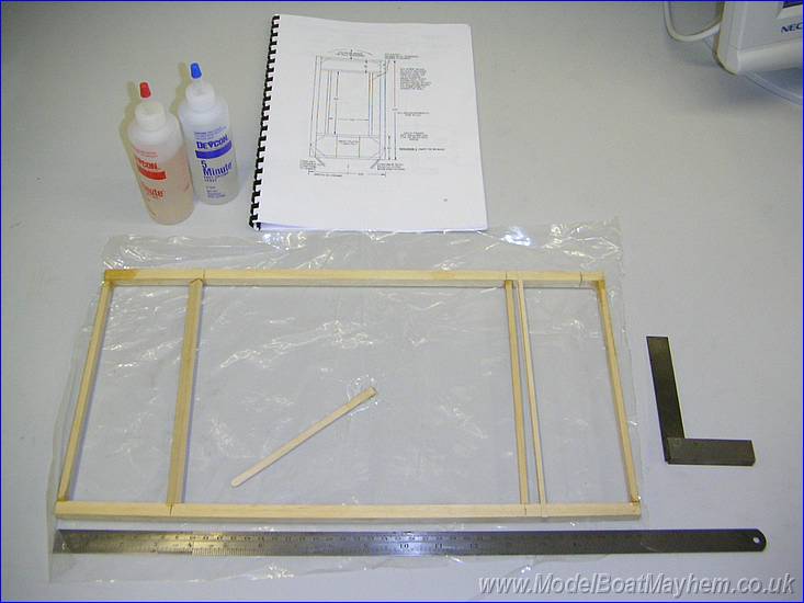
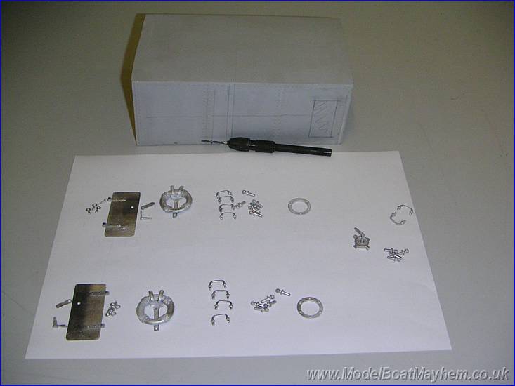
Well after a few weeks of weddings, teeth problems, holidays, work etc, etc. I'm back on the case and we're gonna get this thing built! Next job to do is the rudder and related fittings. Here the parts are laid out over the non-scale diagram. |
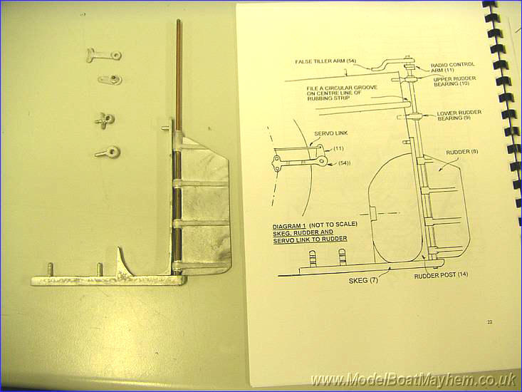 |
Here all the parts can be seen more clearly.
|
 |
|
|
|
|
 |
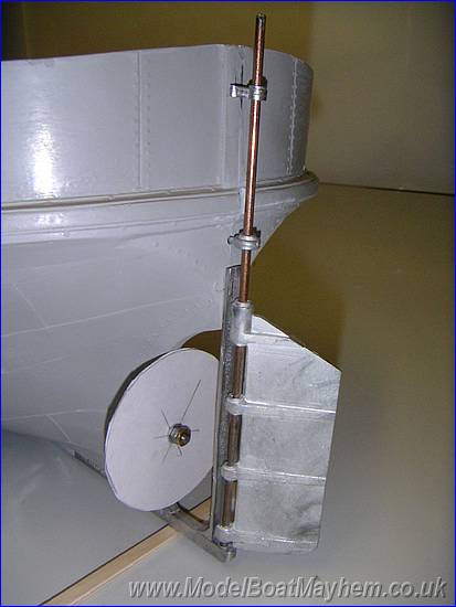
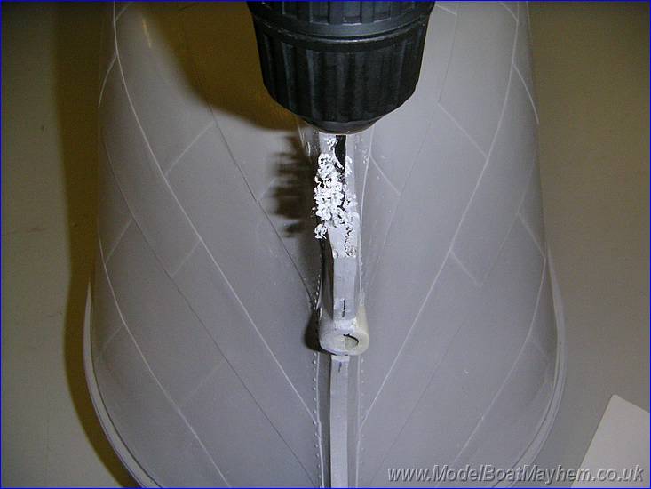
Trial fitting reviled how good the white-metal components are. |
|
|
Trial fitting of the upper bearings.... |
|
|
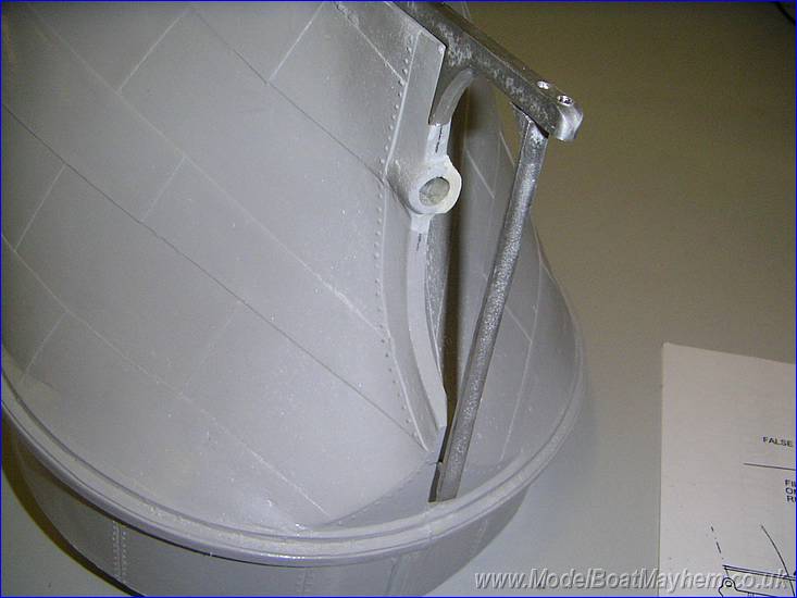
... trial alignment fitting with the dummy propeller..... |
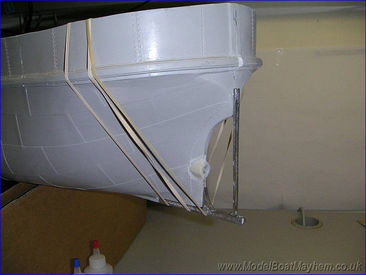 |
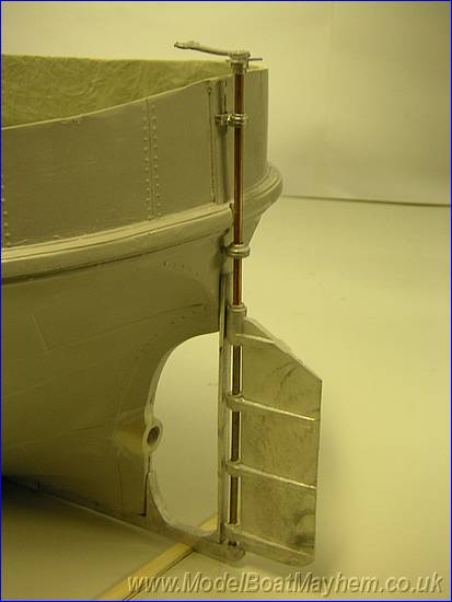
... and being glued in place with 5 minute epoxy. |
|
|
All in place and looking good. |
 |
Next up the inner
deck frame made up of 10 x 10mm timber. |
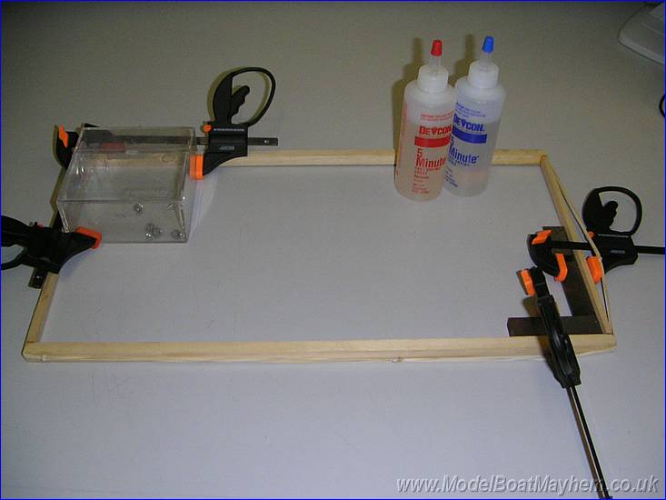 |
Glue up, again with 5 minute epoxy, clamped together against a set square, held with elastic bands around the outside and a empty floppy disk box. |
 |
After the glue had set, I had to cut it free from the work top that it was now fixed firmly too! But no damage except to my pride! The next gluing stages were done on a plastic backing sheet! |
 |
Make sure you understand the non-scale diagram before gluing the bits together. |
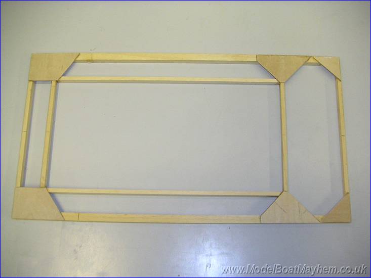 |
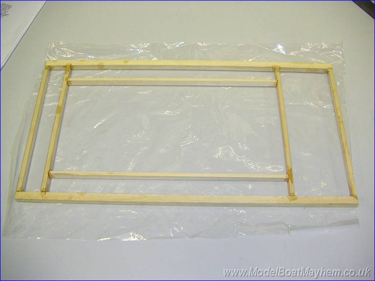
Here it is
complete with corner gussets added. |
 |
|
 |
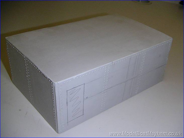
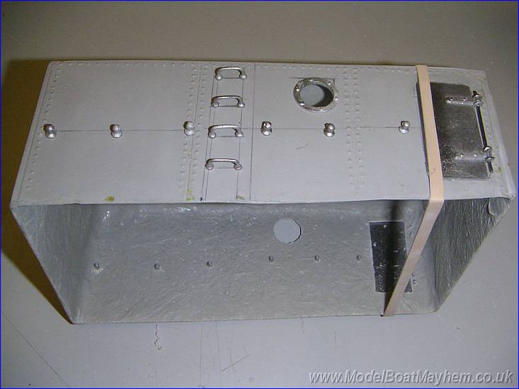
NB: The datum's are the cabin top and cabin rear wall. The diagram for marking out is not clearest one I've ever come across and it's very easy to make mistakes so check everything against the reference photos especially the hand rails were no dimensions are given. |
 |
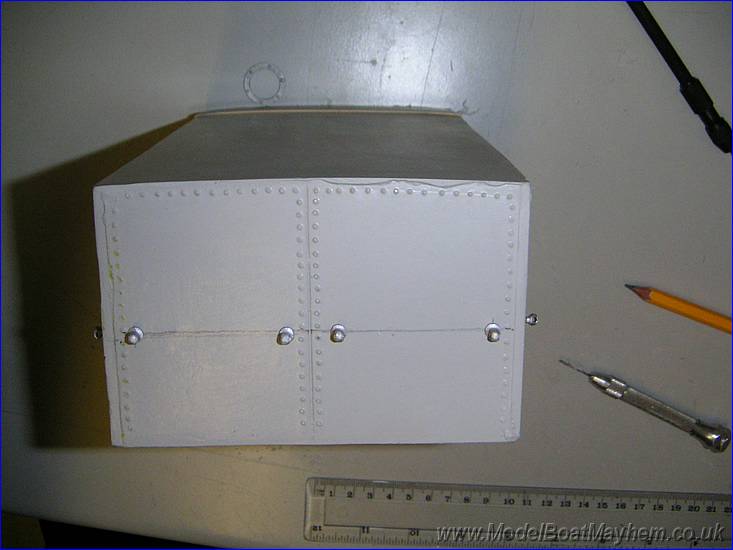
To help with visualising the marking out, all the relevant parts were found in bags and checked against the fibreglass superstructure. |
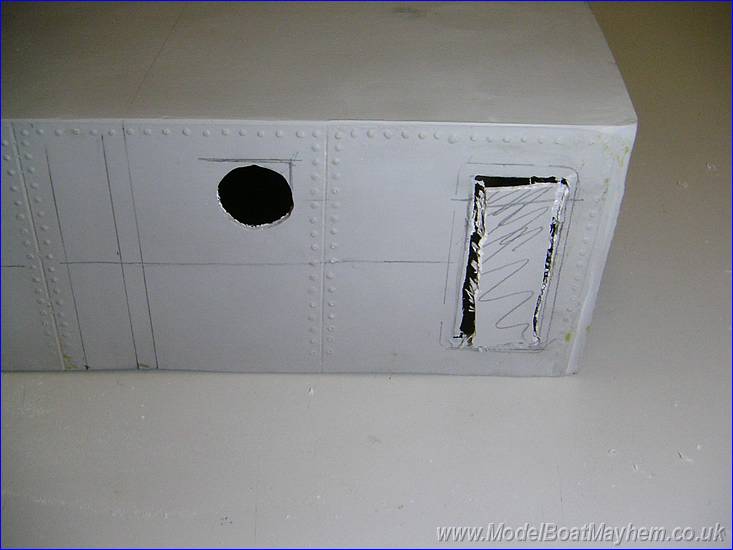 |
The door opening was cup out using a mini drill and a 3mm drill bit used as a milling cutter. Remember to leave the inner lip all around the door as it's a surface mount door. The port hole is cut the same way but to fit the port hole frame flush. |
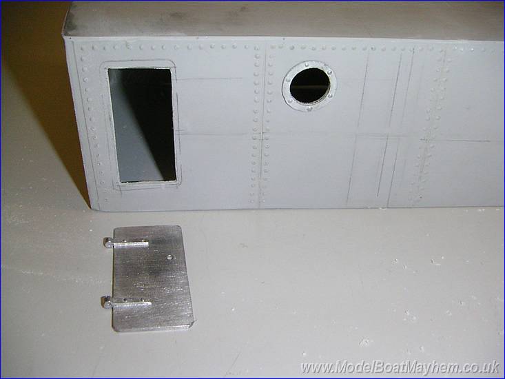 |
The openings are just cleaned up with normal files. |
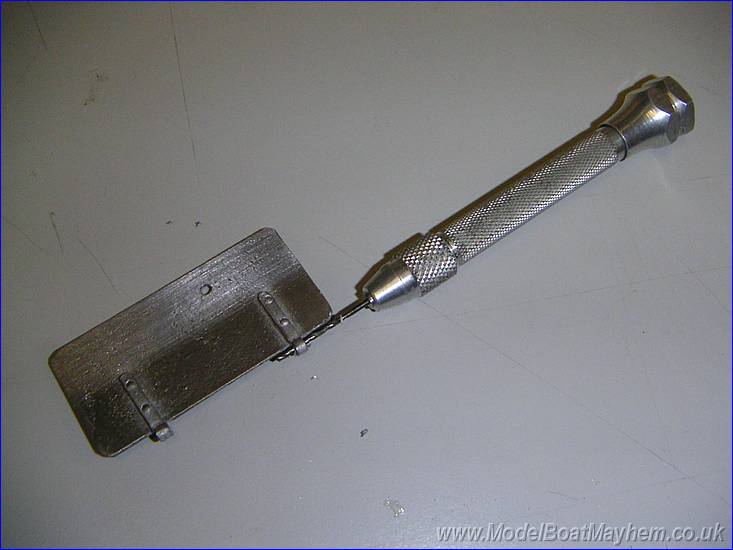 |
The door hinges are open up to take the hinge pins but the eye bolts I don't think they will stand up to and real use and make have to be replaced with home made wire hinges for the sake of robustness. |
 |
The doors fitted for size and held in place with an elastic band. |
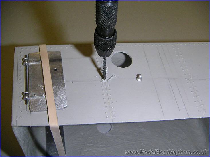 |
With the hand rail holes remember to measure up from the bottom to ensure a constant height from the deck. |
 |
after carefully drilling out all the hand holes and then checking the photos, it soon becomes clear that I hadn't left room for the steering chain pipe and one of the hand holds needs to be moved a bit. |
 |
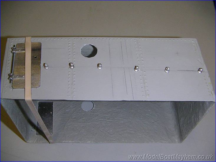
Here's the other side with with the casing steps drilled filled and test fitted. |
 |
The fore end hand rail stanchions fitted but also need to moved down about 10mm, again not shown on the diagram. |
|
|
|
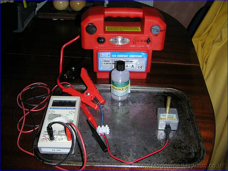
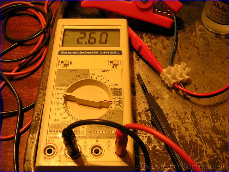
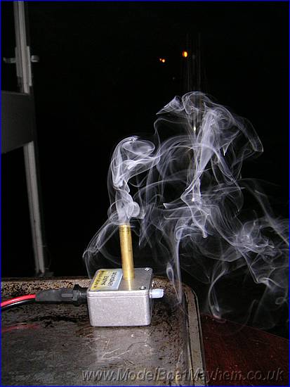
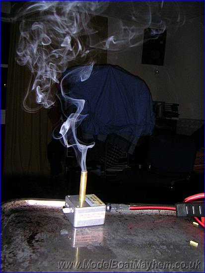
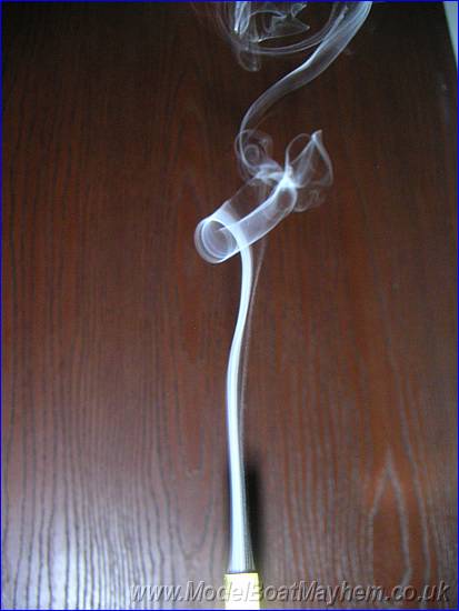
| The Hunter systems smoke unit is quite nice, very difficult to take photos of but very neat and clean... as long as you don't turn it on it's side. Current consumption is 2.6Amps at 12 volts but not to worry as there is lots of room for batteries in the hull. I do have a video of it working but it's 6 Meg long and on it's side... see rule 4 below. | |
|
Rule 1. Measure twice cut (
Drill once) Rule 2. Make sure you understand how the plans, diagrams and photo coincide. Rule 3. Make sure you know what left hard & Right hand door mean. Rule 4. Don't work on a boat when you are more tired than you think you are! |
|
|
|
|