|
9. It's only a winch.... how hard can it be? |
|
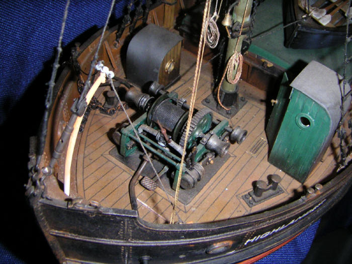 |
Now on to one of the most noticeable deck features, the steam winch up in the bows. Here's a finished winch on Mountfleet's own show model. Easy!...... |
 |
.... and it's as easy as this, Airfix style assembly! "The diagram is largely self explanatory" it says in the instructions.... ....however Mountfleet have not taken into account my outstanding ineptitude! |
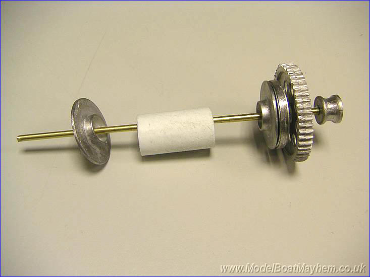 |
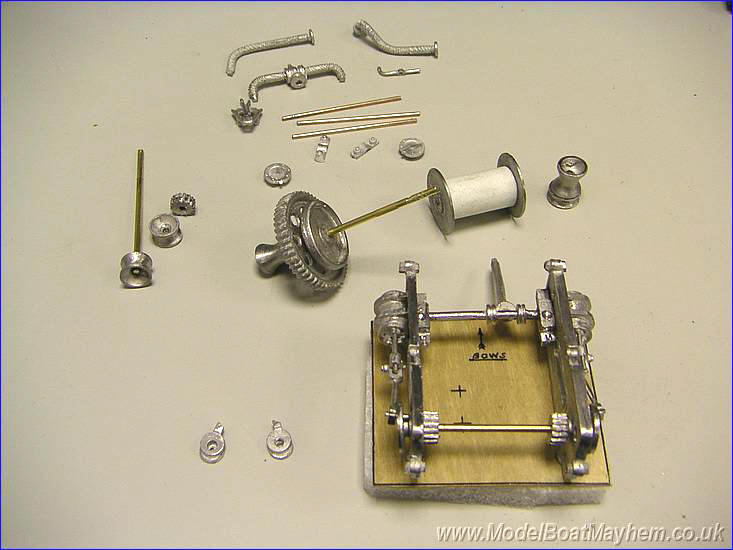
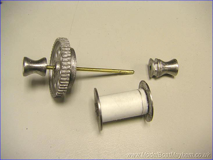
We start off by finding the components for the main drum. Right first problem, the main winding drum is bit of plastic pipe which needs to be cut to the correct length to fit in-between the side frames.... what length? |
 |
Well I guessed at about 28mm and after 2 attempts I had the right length. ( Ignore the fact that the cylinders are actually in in place in the photo, I'm working backwards - journalistic licence! ) |
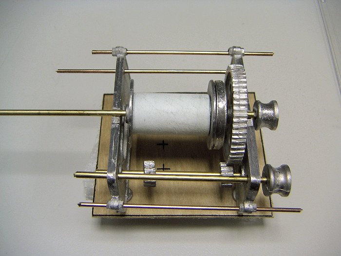 |
The side frames are only sitting in the base plate at the moment so everything was a bit wobbly at the moment, I won't glue anything till I'm sure it right..... but the addition of the tie rods and other shafts makes things more manageable. |
 |
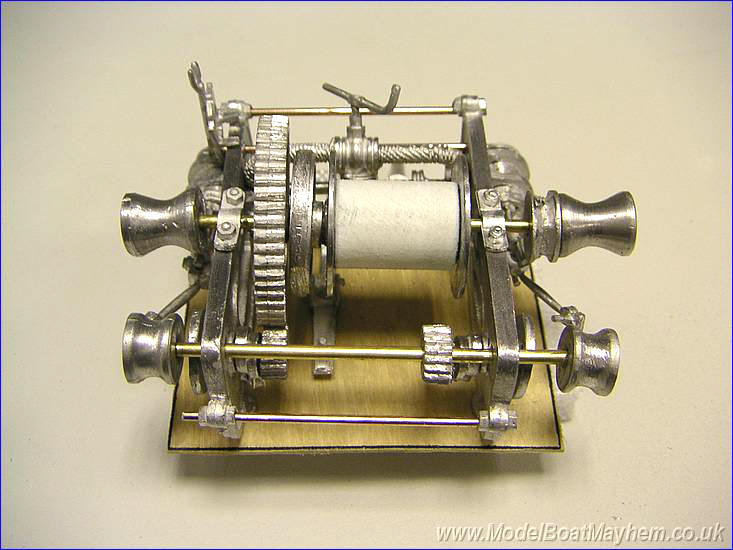
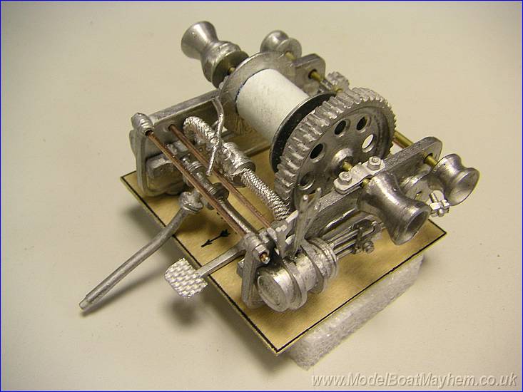
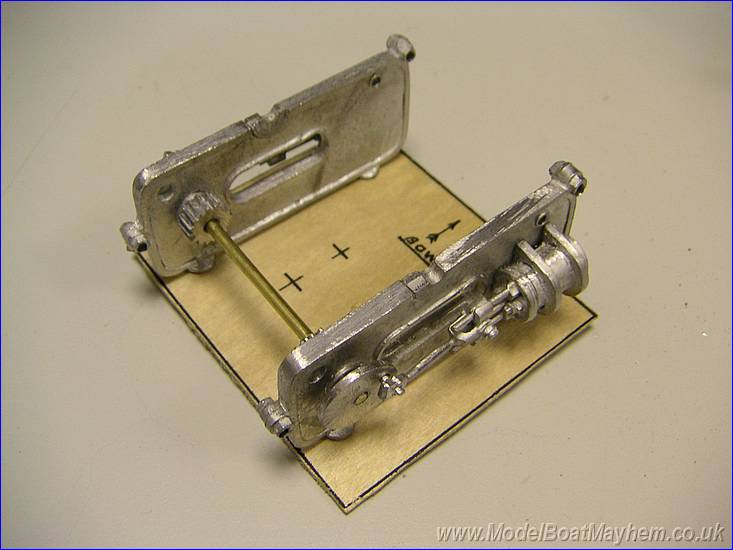
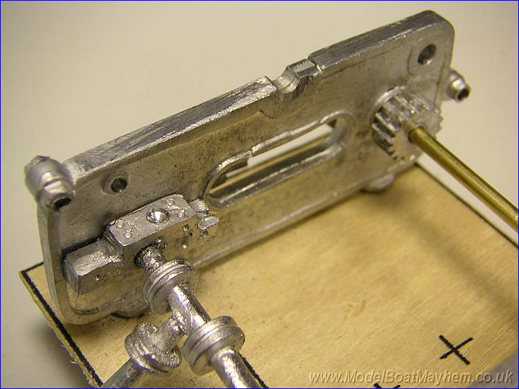
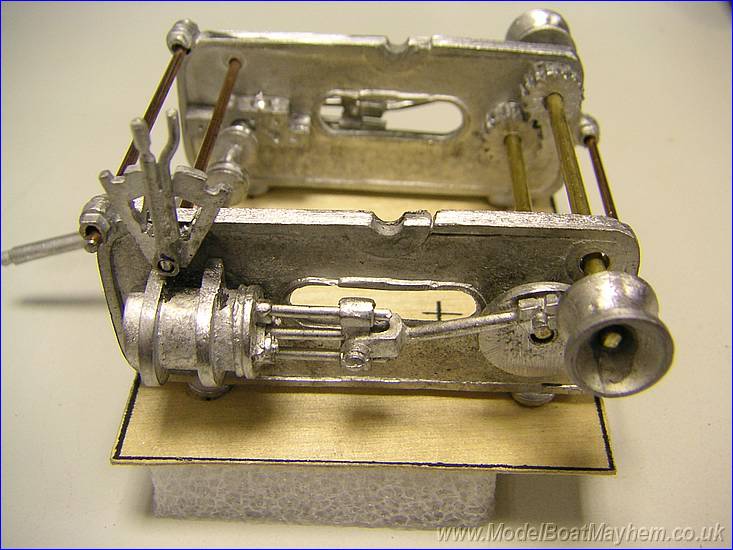
Here you can see that the main drive gear is right up against the right-hand side frame along with the drive pinion on the main drive shaft. |
 |
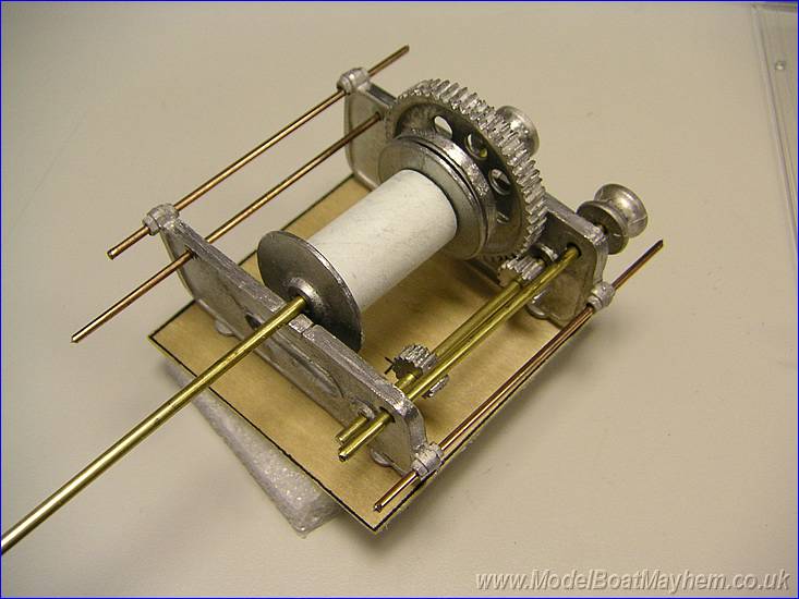
Here from another angle. |
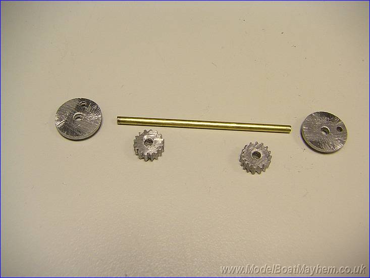 |
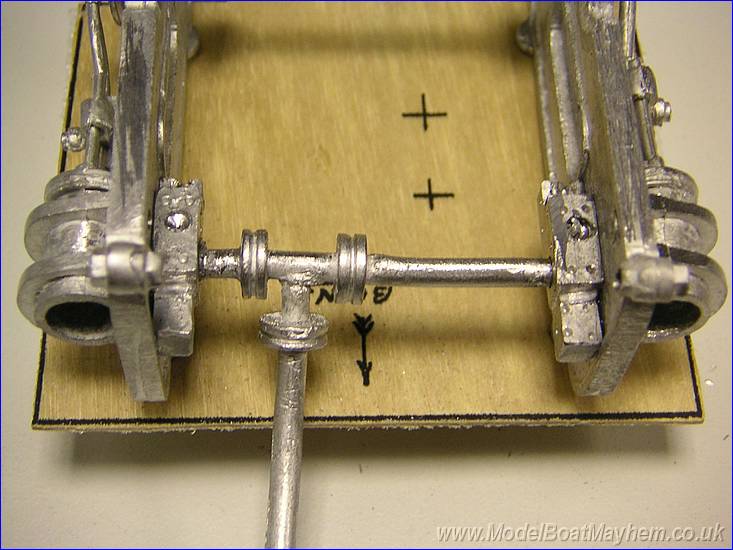
These are the components for the main drive shaft.
|
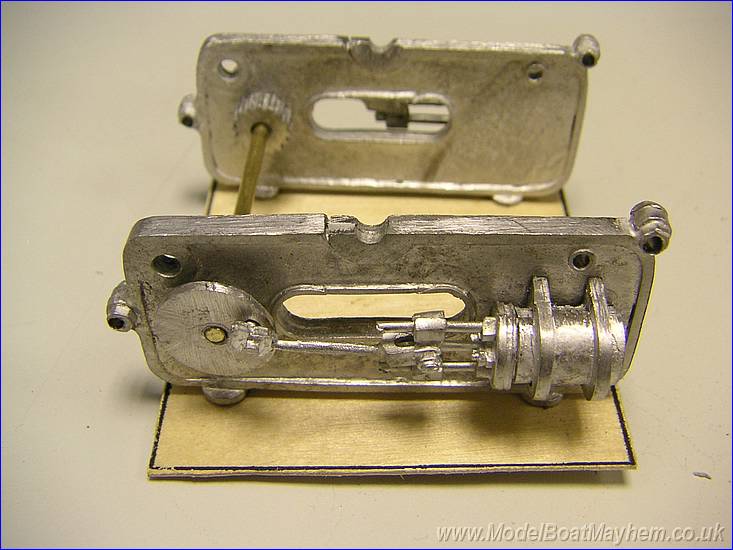 |
The main drive shaft and Cylinders superglued in place.
|
 |
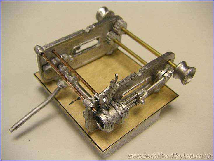
...... from another angle. |
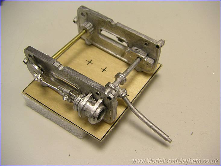 |
The steam chests ( valve gear ) are glued in place and trial fitting of the steam exhaust pipes. ( Don't glue the pipes in place just yet. )
|
 |
 Close ups to show where they go as I found it a bit tricky to read on the
diagram.
Close ups to show where they go as I found it a bit tricky to read on the
diagram. |
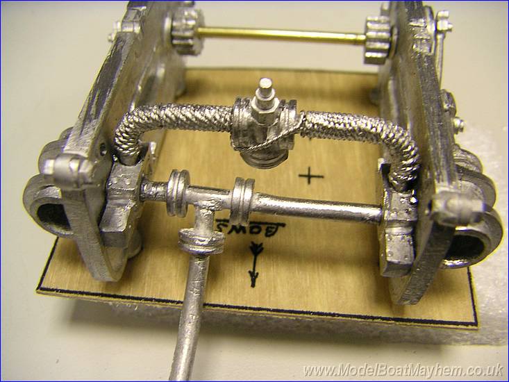 |
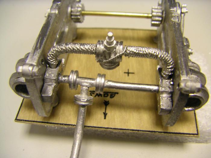
The lagged steam inlet pipes sit on top of the steam chests. |
 |
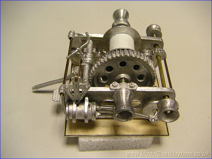
The "jockey" shaft is next, consisting of a another small gear and two rope drums. If the white metal casting where just slightly better, the whole thing would actually mesh and work! |
 |
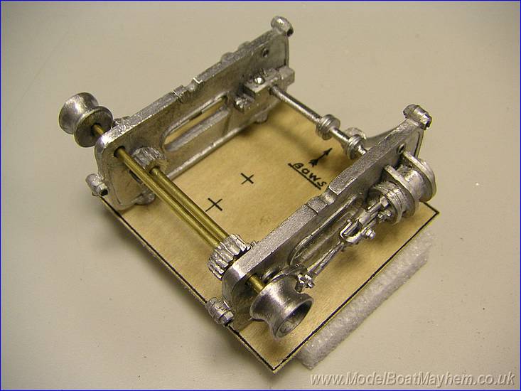
Next a small shaft upon which mounts the "reverse lever & quadrant". I must admit up to this point everything made sense but I can't see how the "reverse lever & quadrant" relate to the steam chests but I suppose not every detail can be included. Never mind, this is where they go. |
 |
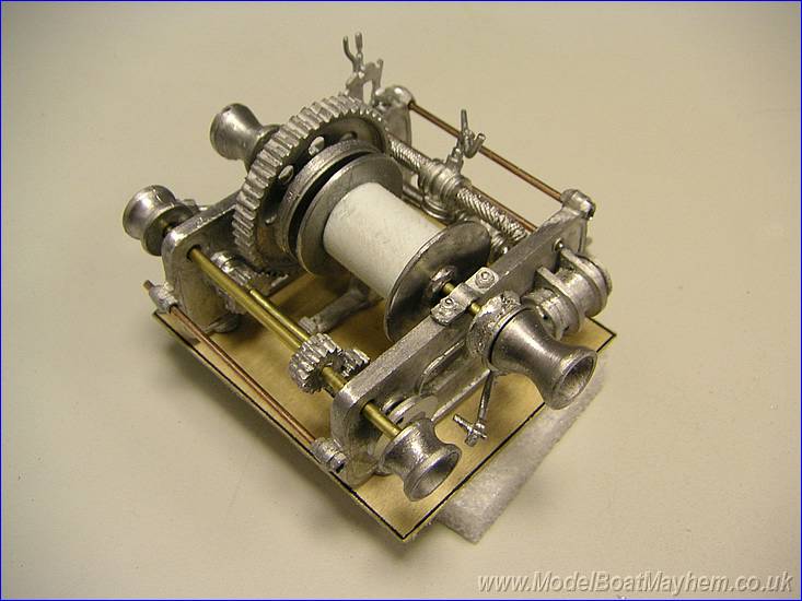
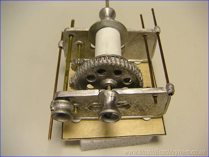
...... from another angle. With everything ready, the crank wheels and gear were glued onto the shaft with superglue along with the "jockey" shaft gear and drums. |
 |
Hang on a minute!
|
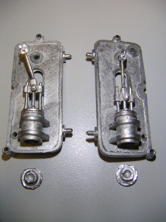
 |
And why are there holes in the end of the cylinders??? |
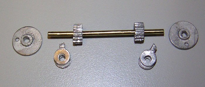 |
Firstly, it turns out that the two parts are the eccentrics that drive the valve gear. Remember that I have now glued on the crank wheels and drive gear to the main drive shaft with superglue. ( Have you ever noticed how quickly superglue set when you don't want it to... like after a mistake or when you are picking your nose!!!. ) |
|
|
Secondly, the cylinder end covers are good fit, I imagine ..... when the cylinders are not glued to the side frames!!! It took an hour of filing and farting around had them in place. |
 |
Well after a long and thoughtful hour, I decided that I couldn't get away with it and the whole thing would have to come apart and re-worked. This would also involve moving the main drive gear along the shaft to compensate for the eccentric... which would then evolve moving the main gear along the main shaft as well ...which would also mean shortening the winding drum again. #*&%$£#@!! |
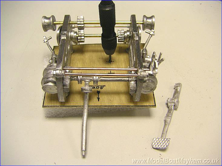 |
Somewhere at this stage, I thought I'd drill the holes for the foot brake pedal...I then realised ( along with all the other mistakes ) that the brake drum was on the wrong way around as it didn't line up with the pedal..... $£#@!!$£#!!$£#@#!! |
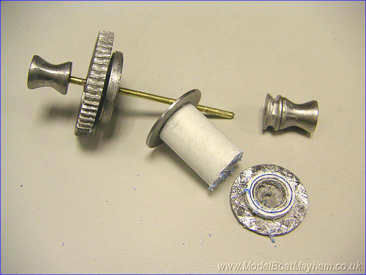 |
In total, I took another 8mm of the drum. I had also not allowed for the "gipsy" wheel ( anchor chain wheel ) so the whole shaft was starting to get very crowed and short! The final length of the drum - at the moment is 20mm |
 |
Have you ever tried to separate white metal components fixed with superglue? It's VERY hard and very time consuming I can tell you! After a lot of manhandling, cajoling, manipulation, prising, twisting, teasing & cursing, the whole lot was back to where it had started 6 hours previously, a winch kit!!!! |
|
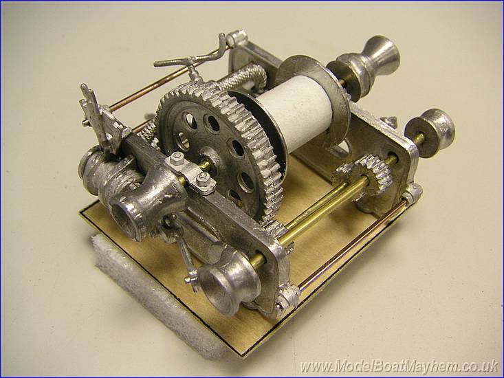
Well...This is the whole thing back together again and everything in it's right place... ready for final gluing.... but not quite ....! |
|
|
|
|
|
A couple more
things to do; |
|
|
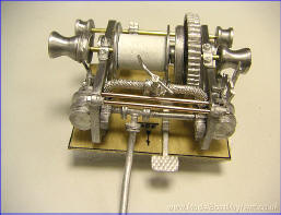
Oh! By the way, this is how big it is! 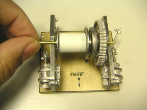 |
|
|
|
|