|
7. Deck hand |
|
 |
|
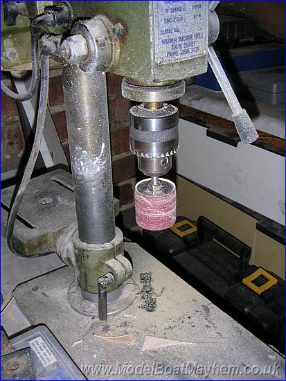 |
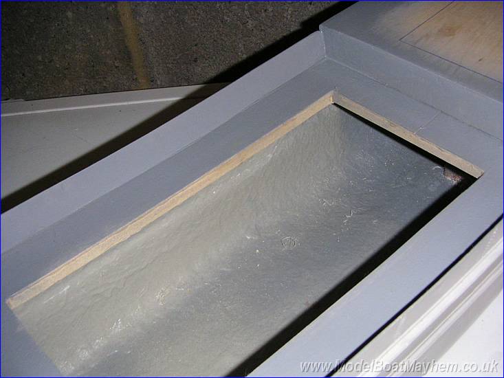
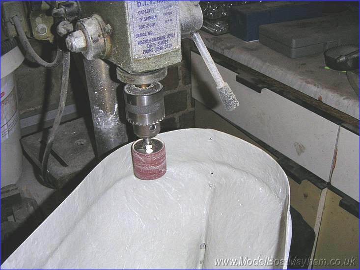
I used a sanding drum in the pillar drill with a 'medium' grade drum which smoothed the inner edges effortlessly. |
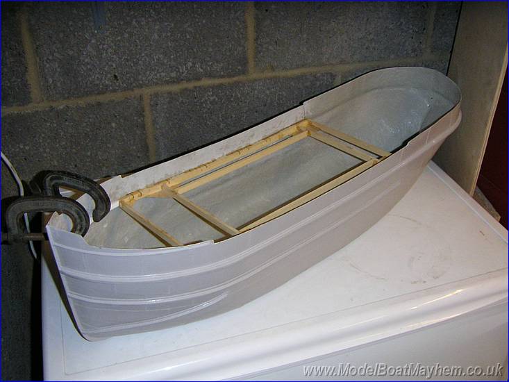 |
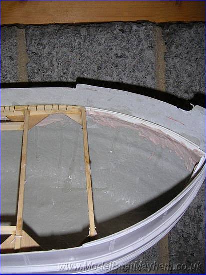
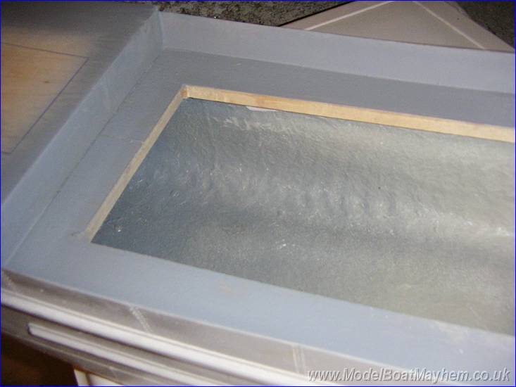
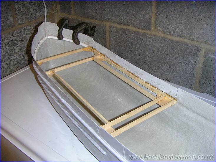
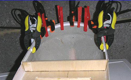
The frame is the first thing to go in the hull - the position is measured from the top edge of the bulwark down (I used a piece of scrap wood as a gauge and drew a pencil line). After marking out I believe the deck is about 5mm higher than it should be i.e. the angle iron pieces that go on to the inner edge of the deck are actually in the wrong place compared to the outside rubbing strip detail, but I decided to go with the instructions. |
 |
The top surface of the two outer
'longerons' of the frame needs lots of little saw cuts made in the top of them.
this allows the frame to be bent upwards at each end making the deck SLIGHTLY concave
(about a 6mm 'dip' in the middle). I Glued with 5 Min epoxy using lots of clamps. be careful not to damage the outside of
the hull. |
 |
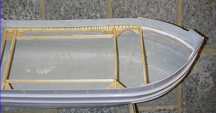
I found a discrepancy in the
instructions when aligning up the frame in the hull, the measurement
from the stern to the frame is 270mm but this would leave the Bulkhead 'J'
hanging in mid air, I reckon the measurement is nearer 260mm.
(I panicked a bit here as Martin had
made the frame and I feared the worst !!!!) |
 |
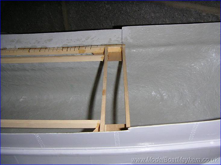
Next the front deck supports. These are made of plastic and were glued in with 5 min epoxy for the first one and the second lamination superglued to the first. I had difficulty understanding where the position of these should be in relation to the bulwark to edge and after some thought these should follow the position of the strake on the outer hull (well that where ours went !) |
|
|
After all of the bits were glued in position I ran a fillet of car body filler around the underside of the supports just to create a stronger joint. (the more filler now...the less ballast later... !). |
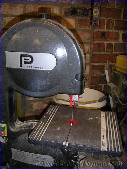 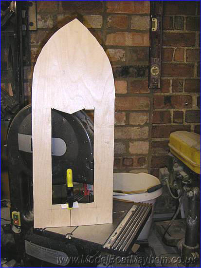 |
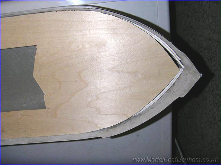
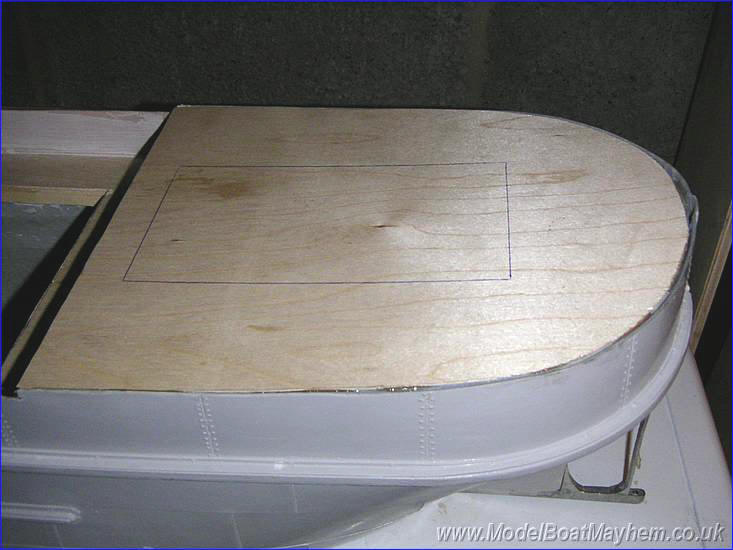
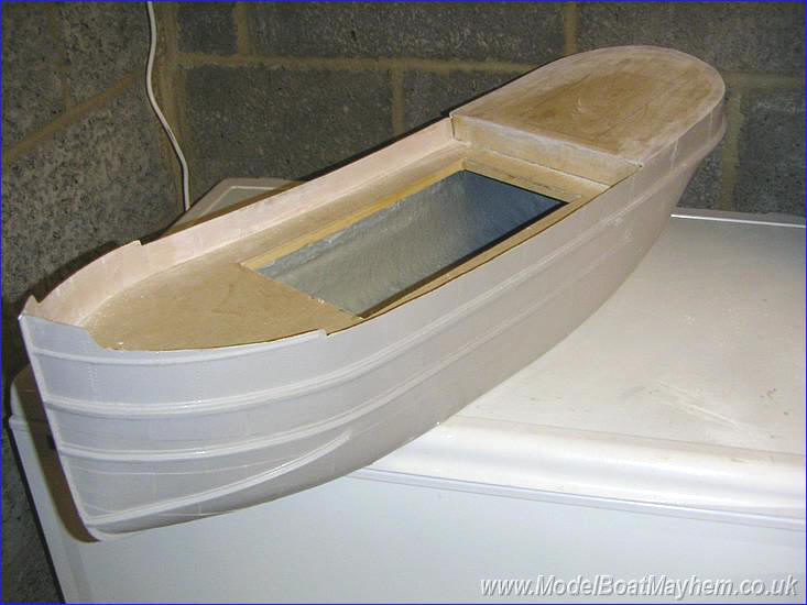
The main deck is
next cut out on my trusty band saw. I cut an entrance through the rear
section and cut out the centre. I just glued a piece of scrap over
the initial entrance cut and will sort this out later. |
|
|
Some cutting and trimming is need to make this deck fit where is should into the hull as, the pre-penned in outline is a very rough guide. (This looks like martin has had a go at it :o) |
|
|
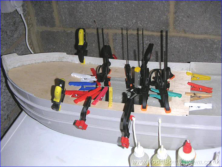
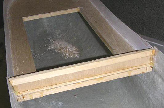
Once the deck is trimmed to size it can be glued down to the frame with PVA glue and epoxy to the hull.... and Lots clamps! |
|
|
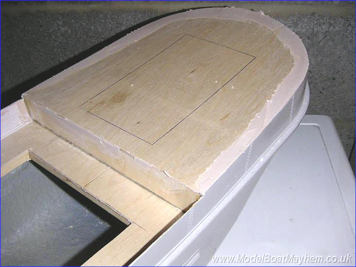
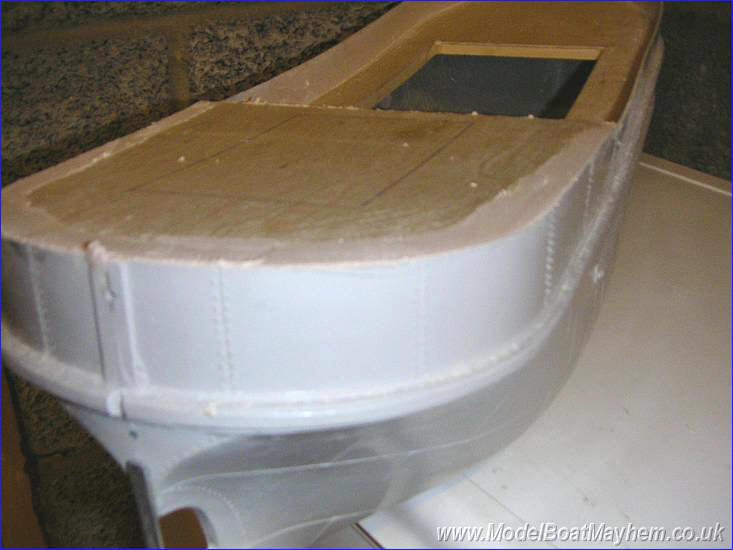
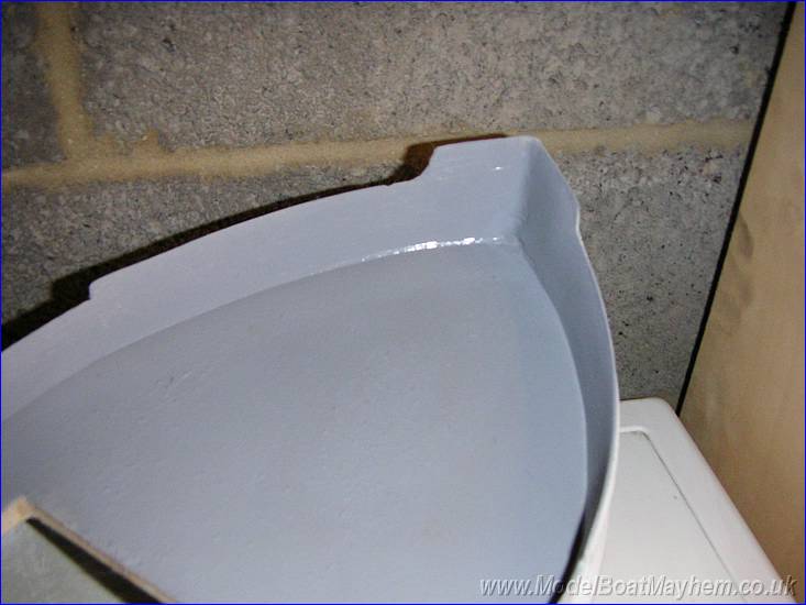
With the deck in place, the bulwarks were skimmed with an initial layer of car body filler. |
|
|
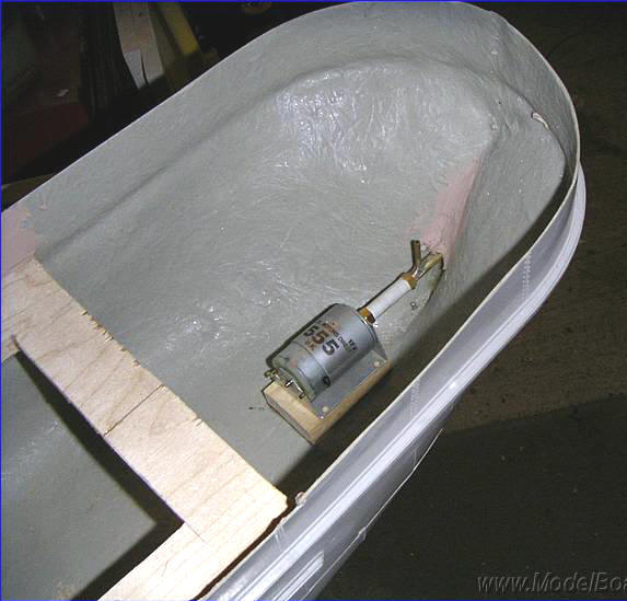
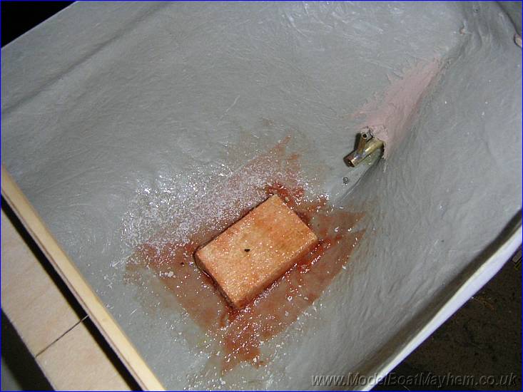
The prop tube was installed at this
point - ("Bit out of sequence there mate!" - Martin ). A wooden platform was made up to the dimensions of the polystyrene block rigid coupling connected and the everything lined up. |
|
|
Once aligned, the prop tube was epoxied in and a support fillet of filler applied. The motor mount was also glued down and a patch of glass fibre matting applied over the top to doubly reinforce it. |
 |
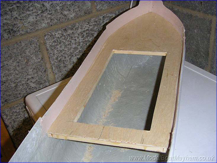
Stern bulkhead plate next. Cut out and trim to size. Liberal amounts of epoxy with avoid the need for the two countersunk screws through the hull!!!!?! |
 |
The quarter deck supports going in. Remember the quarter deck fit flush with the hull.
|
|
|
Test fitting of the quarter deck. As you can see, quite a bit of filling to do! |
|
|
Don't worry about the filler, this deck is meant to be metal, the printed wooded fits on top.
|
|
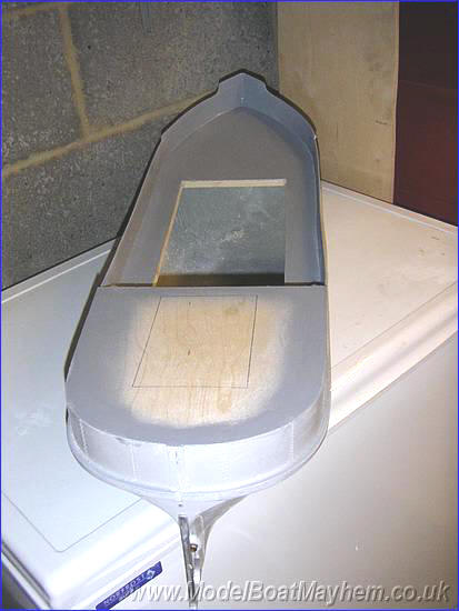
Filling the gaps and sanding down. |
|
|
|
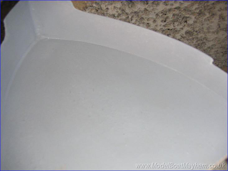
Test priming the hull to see how much extra filling and sanding need to be done."
|
|
|
|
|
|
|