|
Back to Electrical Index
|
|
SPEED CONTROLLERS |
|
Right, you've now got your motor and batteries, some sort of speed control is a good idea. As I said earlier the motors used by boaters are DC. This means if we control the voltage and polarity supplied to the motor, we can control it's speed and direction, useful huh? |
| Choosing a speed controller - What do I need? |
|
From this
you can deduce what ESC rating and fuse to use... ( some digital meter
even have a ' peak hold' where they memorize the highest peak or current
draw ), you can also do a stall test this way too and find out the current
draw if required - don't do a stall test with your speed controller in
circuit, you'll burn it out and don't stick your fingers in the propeller
to try to stall the motor, you'll only end up with fewer fingers!!.
If you are experimenting with the boat set up
you and are changing props, you will need to measure the current draw again and again as any little
change may increase the 'normal' current draw ). |
|
|
| Three types of speed controllers. |
|
|
|
|
|
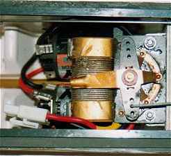
Mechanical or
resistive controllers offer a wider range of speeds than switches. There
are three basic types of resistive controllers, coil wound, switcher with
separate resisters and resistive track. Coil wound controllers are very
robust but they are prone to sticking and generate a lot of heat, (see my
article on the MFA Piranha). If you have a burn-up, a glass fibre pencil
can be used to clean up the controller, check the mechanical contacts are
in good order and that the nut is tight. Lubricate all moving parts with a
little silicon grease. Switcher type resistive controls are similar,
providing three speeds forwards and back and stop. Switcher controllers
generate less heat than coil types and seem less prone to burn ups
although you can blow the resister. The resister should be in free air as
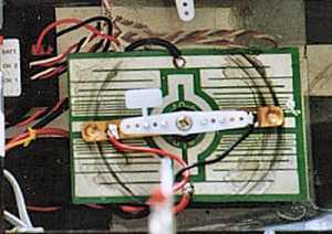
it can get quite hot. Resistive track or wiper board controllers such as "Varispeed"
AKA "Bob's Boards" are very simple to install and maintain (it stuck
straight on top of a servo) but are only rated up to 8 Amps. The average
540 will easily draw that and most will happily draw 15-20 Amps. Having
said that, I've used an 8 Amp Bob's board on a 12 cell - 550 set-up with
no visible signs of distress at all, (See Graupner Hydrospeed). |
|
I've used
Bob's board controllers many
times,
so I dwell on them a while. They are most suited to low Amp installations
such as scale boat because their limited current range but do offer quite
good control. You need to choose the nearest rated board for your
installation so as to obtain the highest amount of control. Connect up
your motor, battery and a meter (set on Amps) and slow down the motor with
your fingers, this will give you an idea of what the current drain for the
motor under load will be. If it stalls at 2.5 A, choose the 2 amp board,
hopefully you'll never stall the motor in real life. A 3 or 4 Amp board
will work but offer less slow speed control. My only criticism of these
boards is the shorting out of the motor at the 'all stop' position. This
is used I assume for motor braking in car applications. Unfortunately when
an electrical motor is disconnected from the power and is slowing down it
begins producing electricity. So shorting out the motor will cause arcing,
damaging the motor and/or 'Bob's board'. Fortunately this is easily cured
by making a small cut across the centre track which leaves the motor
circuit open while slowing down. Again a small dab of silicon grease on
all the mechanical contacts will inhibit arcing and corrosions. There is
another type of resistive track controllers, these have separate resisters
mounted on the underside of the board, these have a tendency to wear
quickly as the copper track is quite thin. |
|
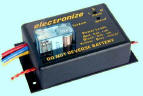
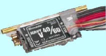
E S C's - ELECTRONIC SPEED CONTROLLERS |
|
|
|
Theses
controllers are a different kettle of fish altogether. The first thing
that strikes you about some ESC are the astronomical price but many are
now down to realistic prices, some under �20 (GB) which is cheaper than a
servo and mechanical controller! ESC provide the best motor control
possible and many have fully automatic setup. ESC's control the voltage to
the motor electronically thus varying the speed. Some of the latest
microprocessor ESC's have all sorts of useful features such as soft start,
variable frequency, speed curves, thermal shutdown, water cooling It's not
actually the voltage that is varied to control the motor but we haven't
got another 20 pages to go into the intricacies. ESC eliminate the need of a throttle servo and optionally the receiver batteries as well. Some ESC's are the same size and shape as normal servos so as to facilitate a direct replacement. The main advantages of an ESC in a sports boat is their phenomenal power handling capabilities, their small size (in some cases) and accurate control, (the latter is more useful in a scale boat). The disadvantages of ESC are, apart from cost, is the danger of a burnt out if you do something silly, destroying it by getting it wet, a limited voltage range (which inhibits experimenting) and potential volt loss across the ESC. (See upgrading below.) |
|
Terms
associated with electronic speed controllers are: POWER RATING Expressed in Amps and volts, tell you the maximum power the unit can handle. Output current rating will have a continuous value and peak or surge value, the peak value only applies for VERY short durations. |
|
PROPORTION
CONTROL Same as a servo. The speed output of the ESC varies by the amount the stick is moved. |
|
FET. FIELD
EFFECT TRANSISTORS
Refers to the type of the power transistors used, sometimes called MOS-FETs. FET transistors are very efficient and so less power is lost as heat compared to normal transistors. Some FET ESC seem powerful enough to handle the output from an electricity sub station! |
|
NB. From Allan -
www.astecmodels.co.uk
This is down to the fact
that an FET is rated at 25deg c if you keep it at that and the innards
about 20 c higher then it will run at the rated current. There are many
FET's now that will run 80-100 amps each. So put 3 in a speed controller
and you get 240amps�� but only if the FET's stay cool - which without a 6
inch square heatsink each they won't. |
|
BEC, BATTERY ELIMINATOR CIRCUIT The ESC uses the main batteries to supply 6v to the receiver and rudder servo as well as the motor. The ESC plugs in where you would normally plug in the throttle servo. A servo has three wires, +ve Red, -ve black & signal or control wire white. The BEC circuit supplies the voltage to the receiver via the red & black and in turn the receiver controls the speed controller via the white wire. The plug can be changed on the ESC to match your receiver but make sure you wire it up correctly, it should be the same as the rudder servo. When running with BEC, as soon as you notice a drop off in motor speed, it's time to bring the boat in as the boat will soon become very erratic when there is not enough voltage to keep the receiver in control. Some ESC shut down when the voltage drops too low, very annoying when the boat is the other side of the lake! |
|
FORWARD ONLY
Self explanatory, not much good for boats as you can't back out of the weeds, but does reduce the price of a ESC. BRAKE, not much use with boats. Forces the motor to slow down when throttle stick is in neutral, not much use on a boat. (See Bob's board above). |
|
REGENERATIVE
CIRCUIT
Not much use either. Uses the current produced by the motor slowing down to top-up the batteries. In theory, if you allowed a radio controlled car to roll down a long and steep enough hill, this feature would re-charge the batteries. Only trouble is, most boats don't have wheels and very few lakes are on a slant. TORQUE ADJUST. Limits the maximum current to the motor. Useful when experimenting. |
|
HIGH FREQUENCY
SWITCHING ESC Basically offer much smoother response for Electronic Speed controllers These ESC are known as "squeelers or whistlers". When you hear one, you'll know why. |
|
If your ESC has a forwards and reverse mode, it is very important to get the boat going forward when the controllers is in forward mode. Many ESC do not handle as much current in reverse as forwards. If your motor/ESC is connected up the wrong way round, the model will work but you can overload the ESC causing a burn out. Some ESC have a LED that lights up when the ESC is in reverse mode which tells you straight away. If your ESC doesn't have a LED then the ESC's wiring diagram will indicate the +ve and -ve wires to the motor. The motors on all speed boats should rotate anti-clockwise (unless you're using a pulley drive but no one ever does!). |
|
Touch the
battery wires direct to the motor so that it runs anti-clockwise and mark
the motor terminals corresponding to +ve & -ve. Once you know which way
the motors need to turn, set the boat up on it's stand, connect up the
receiver, ESC and motor. BE VERY CAREFUL TO GET THE ESC POSITIVE AND NEGATIVE WIRES THE RIGHT WAY ROUND TO THE BATTERY. YOU WILL ONLY GET ONE CHANCE TO DO THIS!
Turn on the transmitter then connect main batteries to the
ESC. If everything is OK, the motor will twitch or spin for a second or so
and then stop. If the motor continues to run adjust the transmitter
throttle and trim until the motor stops. (Some ESC's have a centring
control that may also need to be set-up, also check that the throttle
stick is in the middle position if equipped with a two stage neutral.) If
you can't adjust them so the motor stops, unplug everything and re-read in
makers instructions and try again.
|
|
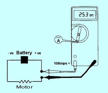
When
everything is OK, connect your volt meter to the motor and battery -ve
wires ( diagram below ), push the throttle stick forward and check the
motor is running forwards (can you feel a draft from the propeller at the
back of the boat?), then check the voltage on the meter, it should 0v or
very low at full throttle. If it is then everything is OK. If the voltage
is 0v but the motor spins the wrong way, then reverse the two motor wires.
If the meter reads +7.2v (or whatever your battery voltage is) and the
motor runs backwards, then just flick the servo reverse switch on the
transmitter and check again. If the meter reads +7.2v but the motor runs
the right way, then the wires to the motor need to be reversed AND flick
the servo reverse switch over on the transmitter throttle (channel 2) and
re-check. There are other ways of checking the mode of the controller but
the above method should work in most cases. |
|
|
|
If your radio Tx doesn't have servo reversers this will involve swapping the wires around on the inside. Unfortunately this option involves tampering with the transmitter and if you don't know what your doing then it's best left alone and asking someone to do it for you. To reverse the servo via the transmitter, remove the cells and open up the back. Look on the back of the rudder stick control, you should see three wires going to it. Make a diagram of the wire and colours, unsolder the two outer wires and swap them over and re-soled. Reassemble the Tx and try it out. The movement on the rudder servo should now be reversed. If it doesn't work, your in trouble and don't blame me! Put everything back as per your diagram and ask someone else to do the modification for you. You may find that the servo output arms have to be re-positioned after the servo is reversed. If you're not sure about all this, DON'T DO IT!!!
Well all of this is just my opinion, but what the hell do I know! |