|
Finding
myself with time on my hands and getting bored with playing 'Minesweeper'
I decided to revive my old hobby of model making, something I haven't done
for about twenty years.
Since my first (and last) aircraft crashed 30 seconds after leaving the
ground and having no interest in cars I decided to build another boat.
Having built electric and glow engine boats in the past I decided on steam
power for this one.
Sourcing engine, boiler, ship, etc was the first step. Kits designed for
steam power are few (The Model Dockyard was one source) but are either
smaller than I wanted or more expensive than I was willing to pay. While
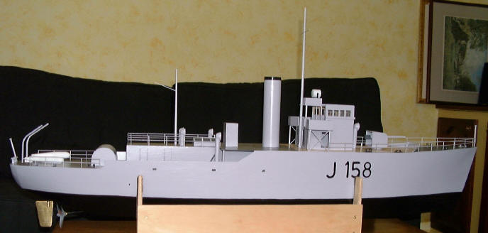
searching ebay for an engine and boiler I came across plans for "Bathurst"
and paid the princely sum of £3.oo for them. These plans comprise a side
view, a plan view and some quite detailed building instructions. The plans
are 1/96th scale and since I wanted something larger I scanned and
reprinted them at double size.
Engine and boiler were even harder to source. Stuart Turner, Cheddar Steam
Models, Model Steam Engines and John Hemmens all supply some lovely
engines and boilers but all are well over my meagre budget. Eventually I
found a company called Forest Classics who deal with a German manufacturer
called Wilesco, they had a suitable engine and boiler for my ship (model
no. D48) at an affordable price, less than £200.00. This is a
self-starting engine with forward/reverse & speed control and twin
double-acting cylinders giving four power strokes per revolution.
The plans suggested using all balsa for construction and electric power -
I had to make changes, I didn't think balsa would be strong enough
considering size and weight of engine and boiler so I substituted 3/8ths
marine ply for the main hull parts; flat base, decks and bulkheads, and
1/16th ply for side skins.
The plan showed three access holes in the deck, one at the stern for
rudder, one in the middle for motor and one under the bridge for radio,
batteries, etc, only the rudder hole didn't need enlarging. The motor hole
had to be wider to allow fitting of the engine but access for the boiler
needed to be considerably larger than the plan. Only a single bulkhead was
shown in the plan so for increased strength I added two more, one at the
rear of the engine access and one halfway from centre to bow so I now had
four seperate compartments which proved to be very worth while.
With the basic frame of the hull constructed (without side skins) I began
to think about the problems of using steam in an enclosed ship.
First thought was what to do with the steam exhaust, then what about water
and steam leaks from the engine itself and finally what to do with
combustion gasses coming from the gas powered boiler.
Taking these problems in order I built a small 'condenser' unit from some
copper pipe. This is simply a 22mm end cap, a 22-15mm reducer, a 15-10mm
reducer and a short length of 10mm pipe all soldered together. I drilled a
couple of holes in the side and solder two short lengths of 1/8th diameter
pipe into it, one pipe takes the exhaust, the other drains off condensate.
Next came a tray for the engine to sit in, some thin copper plate which I
had lying around came in handy, cut and soldered together it makes a
simple sump for the engine. Another piece of 1/8th pipe soldered into it
allowed me to connect the condenser to it so all the water would end up in
the sump.
The copper plate came in handy again for making a cowl to sit over the
boiler. Although this may not be strictly necessary I made it anyway.
Complete with a short length of 22mm pipe it guarantees that most
combustion gasses go up the funnel. With the condenser sitting under it as
well, steam exhaust is directed up through the funnel as well.
Now, what do I do with all that water sloshing around in the sump under
the engine - a bilge pump was required.
Should I have it running full time? - no the pump doesn't like running dry
so it'll have to be switched. I considered fitting a microswitch close to
the tiller arm to be activated with full left rudder but decided that
would interfere with my sailing. My next plan was for a float switch to
operate the pump - it should have worked but didn't! A micro-switch, a
piece of cork, a few scraps of balsa and some glue and I had a float
switch. Testing proved it was u/s, there isn't enough depth to the sump
tray so back to the drawing board. Enter my brother-in-law, "An electronic
switch is what you need here," he said. Two weeks later he came back with
a device which works perfectly.
Then I thought of another problem with the boiler - I'd dealt with the
combustion gasses but what about air; inside a sealed hull the burner
would be starved of oxygen. I thought about using the ventilators but
since construction of hollow vents is beyond my capabilities and they
would probably be insufficient to deliver enough air I turned to the
bridge house itself. Since this sits directly over the boiler I decided
that making modifications to it was the best option. The bridge is
supposed to be on two levels, the lower level is a sealed box while the
upper level is open to the rear. Instead of drawing the three doors onto
the lower section I cut them out and also left an inch wide gap at the
front of the upper section floor.
The bridge house is supposed to cover the forward access hole but with the
hole enlarged to allow fitting of the boiler more mods were necessary. The
only solution was to create a new forward deck from 1/16th ply. I did this
in four pieces, front and two side sections glued to the existing deck and
one section left removable to cover the access hole. The bridge house,
funnel, vent and gun fit onto this removable section.
Next job was to plan fitting the radio gear. Within a potentially wet
environment I had to protect the electronics. Putting them in a sealed
container in the section forward of the boiler seamed to be the best
solution but that would mean routing control rods past the boiler and
engine. A better solution was to fit everything in the stern section. The
access hole to the rudder is large enough to allow me to make a platform
for the servos and receiver and, since its well away from the steam, a
water tight box wouldn't be necessary. The aerial fits into a plastic tube
glued to the underside of the rear deck. I built a platform to carry the
bilge pump and its control circuit and fitted this at the rear of the
engine section, it proved to a very convenient location for the receiver
battery pack as well.
With all of these problems resolved I did a 'dry run' of fitting
everything inside the hull prior to fitting the side skins. I had to
reassure myself that I would be able to fit the engine, boiler and radio
gear through the access holes. Apart from it being a little bit fiddly,
especially with the engine and its sump tray, everything went in as
planned.
When the hull was complete with its side skins I decided to add a coat of
resin to all it's interior surfaces to protect them from steam and water
should anything untoward happen with the boiler, engine or piping.
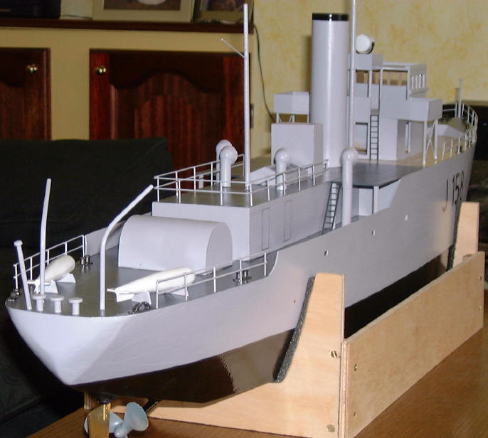
All of the superstructure is made from 3mm balsa except for the
minesweeping winch which is 1/16th ply bent over 3/8th ply sides. Railings
are brass wire soldered up on a little jig that took ten minutes to make
and saved hours of time and burnt fingers. The funnel is a length of
plastic drain pipe. Minesweeping floats were carved from 1/2 inch dowel,
davits are copper tube. Vents, ladders, searchlight, bitts and fairleads
bought from Ashton Models. Three vents were extended for height with 10mm
copper pipe glued together with a short piece of dowel.
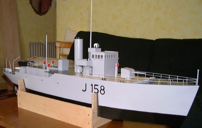
Length is 47 inch, beam 8 inch, height of foredeck 6 1/2 inch, height to
top of foremast 19 1/2 inch.
During design and construction I have had to make many changes to the plan
so it is no longer a 'true' scale model.
For a flat-bottomed boat it is surprisingly stable (at least in the bath).
It requires 2 Kg of ballast to trim, 1/2 Kg at the stern and 1 1/2 at the
bow. Although I haven't weighed it, I guess it to be about 10Kg including
ballast.
In all it's taken me about three months to produce this model and has cost
about £350.00 for materials and equipment, the engine and boiler taking
about a half of this amount.
Photo details:
Engine: At the left you can see the electronic switch to control the bilge
pump and the red control rod for the engine. Hidden beneath this platform
is the receiver battery pack. The blue pipe on the right is the steam
supply to the engine (this pipe is supplied with the engine).
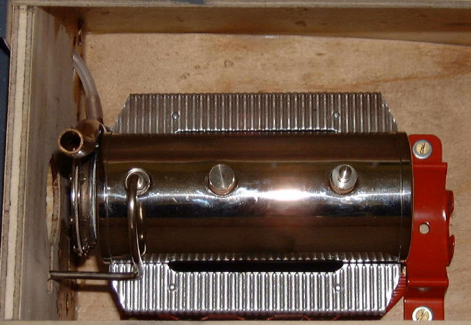
Boiler: (Shown without the cowl) At the left is the top of the condenser
unit and a hole through the bulkhead giving visual access to the boiler
level sight glass. On the right (the red part) is the holder for the gas
tank (supplied with the engine)
Radio: The receiver is hidden under the deck at the right, the black wire
at the top is the aerial going into the tube. Discerning viewers may just
be able to make out the lead ballast hidden under the servos.
A final note:
Anyone who is familiar with this class of vessel will no doubt note
certain omissions. Most notable would be lifeboats (it's like the Titanic
- unsinkable), windlass and anchors, a gun or two, some depth charges and
launchers, etc. I may or may not add these things later (providing I can
find a supplier for reasonably priced and correct scale parts).
|