|
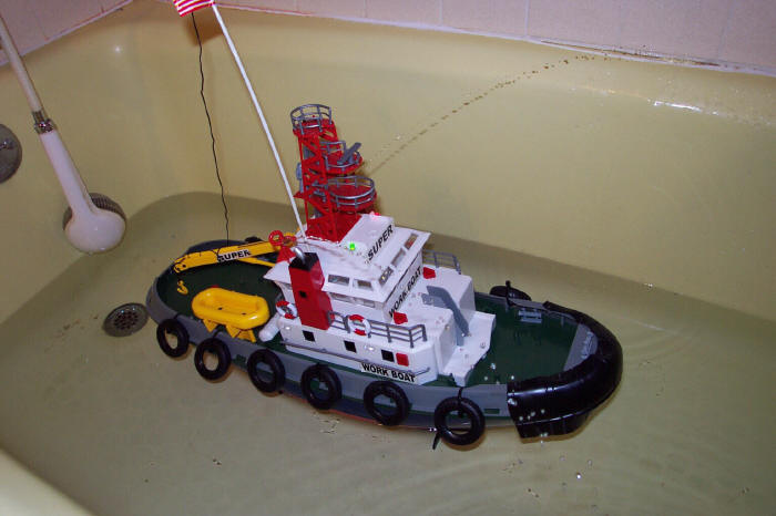
Super
Workboat / Dickie Tug
Length 23 1/2 Inches 600mm
Beam 7 1/2 Inches 190mm
Tug was Purchased on Ebay for about $23 including shipping. I purchased it
for a retrieval tug for my speed boats.
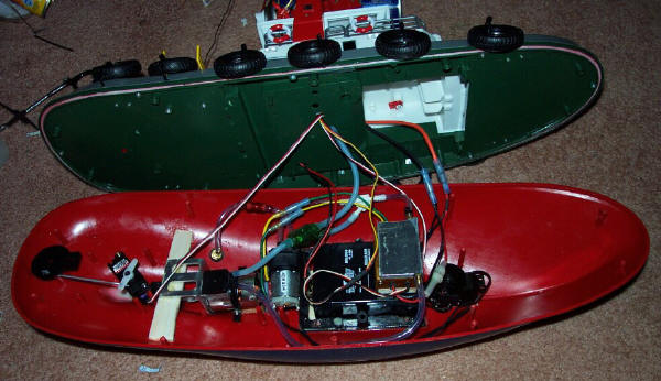
I quickly found that the Hull and Super Structure was great quality but
the Electronics were lacking.
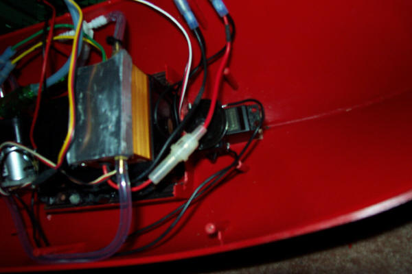
I removed all electronics including Motor and Pump. I also Open the top of
the Ballast Tank and sealed the bottom up.
I then removed the motors yoke and bored it out a bit to fit on a 1/8"
shaft of a 540 Stock 27 turn motor. I have bunches of them from my RC
Cars. Mounted the motor on a Aluminium Motor Mount that I purchased from
http://www.offshoreelectrics.com I then Epoxy a piece of balsa wood that I
bevelled to fit the hull and then epoxy the motor mount upside down to
that. Yes this system does make some noise but mine seems to make a good
loud engine sound that seems pretty realistic for a tug. So I have not
thought of changing the drive train any further.

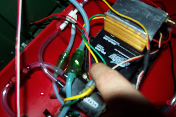
I also installed a Robbe
D37 Water-Cooling Heat Sink that has been silicone to the motor. The Clear
tubing required a bit of silicone and I recommend silicone on the
aluminium where the o-ring is. It leaked a bit on me.
As you can see I mounted a Standard Servo and a Z bent .073 wire for the
steering.
I also Installed a Water Pump MFA 650 6-12 volt pump along with a 1/8" ID
Fuel Filter, You never know what is in the lake and the Monitors will get
clogged if you suck something up.. It flows at a rate about 500ml per
minute at 6 volts. It is mounted to a Piece of Balsa and CA Glued to the
bottom of the boat.
I used a Hitec SP 6/10 amp speed control that I just had around from
something I had purchased a while back.
I also custom made an
Aluminium Water Cooled heat sink. I started with a 12" by 4" piece of 1/4"
thick aluminium I then bored 10 5/32" Holes 1 1/2" deep leaving some space
between each and making sure to leave at least 1/4" space at the end. I
then milled out the aluminium between some of the wholes to allow water to
pass from 1 to the next. Creating like a snake effect on the water going
back and forth. I then cut the aluminium block out of the larger block
making sure to leave 1/4" for the fitting to be put in on the ends. I then
milled the other side. I then drilled a whole at each end with a #21 Drill
bit and then taped it with 10-32 tap for a 10/32 Threaded barbed fitting.
I then Caped the Top and bottom to seal it with a piece of sheet aluminium
with JB Weld epoxy. Putting Light Clamp pressure. Make sure to use some
Thread Sealant or Teflon tape on the Fittings. And test if for leaks
before mounting it on a Speed Control.
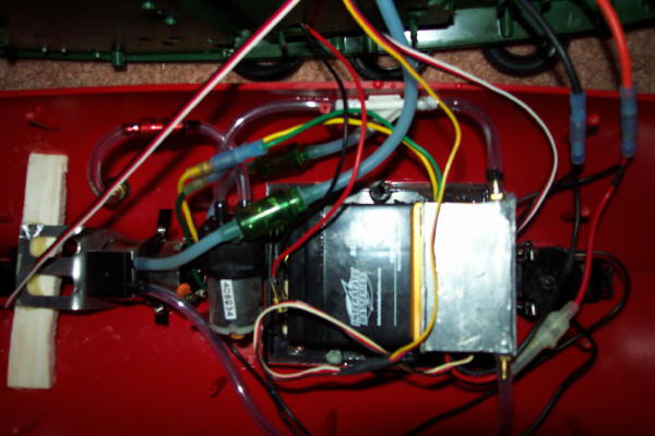
I used a 4.5ah 6 Volt
battery that provides plenty of ballast. It weighs about 1.8 lbs or 725
grams. If you are looking for more thrust or Bollard Pull then you should
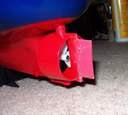
go to 12 volt NiMH and use a 4 Bladed 50mm LH Brass Prop with a 2.5:1
Reduction 600/24 Motor. You may need to remove and install a new brass
tube. Heating it is most likely the easiest way of getting it out.
The MFA 650 Pump has several purposes it Cools the Motor and ESC and it
Shoots water out of the 2 Graupner 337 Monitors that replaced the fake
monitors. It requires no modifications to mount them. Just need to enlarge
the hole in the bottom deck for the water line.
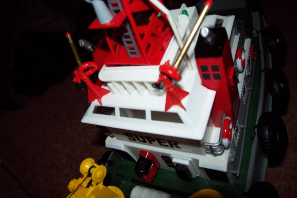
I used a 3/16" Vacuum T
from an automotive store to connect them up. They are Fixed but are really
just for show. They also look like they belong on the tug.
You may have noticed in the picture above to the left of the on and off
switch. Those are banana Plug jacks for Charging the battery. I also
thought those looked like water hook-ups and seem to fit in with the boat.
I am using a Radio Shack 6 Volt 800ma Power Adapter for the Charger. It is
a Universal Power Adapter and has a Impedance Circuit to limit the
Milliamps. As the Charge Reaches about 7.1 to 7.3 Volts it shuts down or
lowers the Milliamp Push. According to Interstate Battery that Supplied
the 4.5ah battery this is a good way of charging it.
Now for a little more technical stuff. Due to the fact that the boat is 6
volts you can run your RX off of it. I recommend this cause BEC are not
all that reliable so if your ESC has a BEC disconnect the RED power wire
from the servo connection off of it to then use a Battery connector to the
switch inside to power the RX. You can Also Hook-up the Lights direct to 6
Volts plenty bright.
The Servo up front controls
the Pump. The MFA 650 is reversible. I used 2 micro switches to allow it
to go in both directions. And Allows you to Clean out the Filter by
reversing it and use it as a bilge pump as you will see down below.
To wire the micro switches you need to find the Common terminal. Use a
Multi Meter to check for continuity. Check to find the 2 terminals that
are connected when the Switch is at rest and when the switch is triggered.
The 1 in common is the Common terminal.
The Uncommon Terminal when at Rest is the - the Uncommon terminal when
Triggered is the + on both micro switches to the Battery. Then connect 1
wire from the motor to each Common terminal.
I used a Degree Wheel that comes with the servo that I cut and bevelled to
allow me to use the trim adjustment to cut it on or off Pump in or out.
And then Either Glue or very Carefully Screw the micro switch to the
servo.
I have chose to make a Bilge pump out of it by installing 2 Aquarium Check
Valves (1 way Valve).
The Check valve on the
right allows water to go up to the Monitors but not back. The Check Valve
on the Left that is coming off the 3/16" Vacuum Y Fitting will only allow
water to flow toward the Y Fitting. The line coming off of that goes to
the bilge area under the Motor. When you reverse the Pump it will suck any
water out of the bilge. It also will flush out the filter. I should note
my boat never leaks I keep a little oil on the Prop shaft and never needed
the Bilge Pump.
I also extended the rudder
I need to get some red paint. The paint said red but it came out a bit to
pink.
To create a reverse with
2 Micro Switches.
-
The at rest uncommon
terminals on both should be –
-
The Triggered uncommon
terminals on both should be +
-
Wire 1 wire off the
motor to each of the Common Terminal
When neither micro
switch is triggered both terminals on the motor are – when you trigger 1
switch it sends a + to the motor Completing the Circuit and turning in 1
direction or the other.
Here are some of the Parts I used to make this tug.
Balsa Wood
1 Banana Plug Terminal for Charging ( Electronic Store )
1 6 Volt Wall Adapter 500 to 2000ma and 2 Banana Plugs
1 Stock 27 Turn 540 Motor
1 Aluminum Motor Mount from
http://www.offshoreelectrics.com
1 MFA 650 Pump from
http://www.pandanmodelboats.co.uk/
1 Raboesch - Brass Water Cooling Inlet/Outlet
http://www.pandanmodelboats.co.uk/
1 Robbe D37 Motor Water Cooling Heat Sink
http://www.pandanmodelboats.co.uk/
1 4 channel Stick Radio with 2 Servos
2 5amp Micro switches for the Pump
1 Hitec Reverse 10/6 amp speed Control
1 6 Volt Lead Acid Battery (3 to 4.5 ah)
2 Aquarium Check Valves (1 Way Valve)
1 3/16” Vacuum T Fitting (auto parts Store)
1 3/16” Vacuum Y Fitting (auto parts Store)
1 Package of Graupner Part# 337 Monitors (2 monitors per package)
http://www.harbormodels.com
2 Brass 10/32 Threaded Barbed Fittings for the Custom Aluminum
Water-cooled Heat sink
http://www.towerhobbies.com
|