|
PIRANHA Mk I - MFA/Cosmo drills
|
|
Source:Kit:Accessories:
|
Most model shops & mail order. £35 £40 (motor, speed control & batteries) + radio. Superseded by Mk II |
|
|
|
|
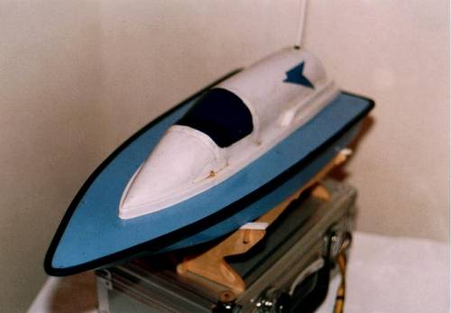
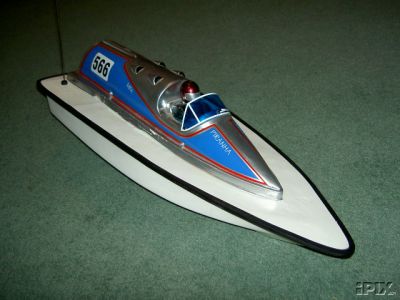
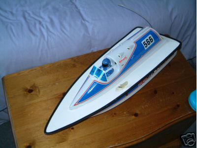
The MFA Piranha 2 is a compact high performance powerboat. 570mm long, with a 230mm beam, the Piranha 2 is designed to take 2-channel radio control. two versions of the kit exist; one for electric power, using MFA's own "Rocket 500" powerpack; and one for I/C power, using a 12 size (2.1cc) 2-stroke engine. Both versions are tough fibreglass - not the plastic that some other smaller powerboats are made of. Complete kit - requires only engine or motor, plus 2-channel radio.
|
|
|
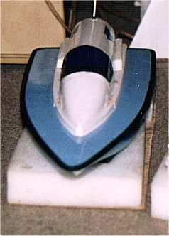
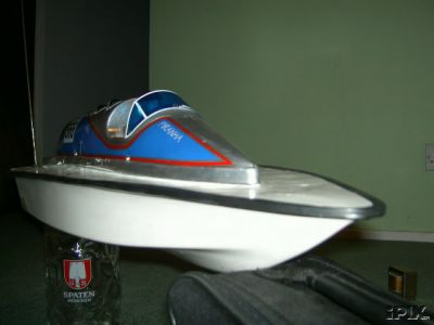
STYLING
The boat is about 570 x 230mm in fibreglass. Fibreglass is usually known as GRP which stands for Glass Reinforced Plastic. The top bit (white) is made of styrene, a thin plastic similar to the stuff margarine tubs are made from. The Piranha's hull is a Vee at the front merging to flat at the transom. The boat is designed for the MFA Hummingbird '15 or 20' which are 540-550 sized electric motors, 8 cells (9.6v) and 2 channel radio.
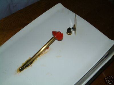
The instruction leaflet seem to assume you already have some boat modelling experience but are good enough to get the beginner and the boat to the water without too much trouble. The included plan is full size so measurements can be transferred directly to the boat, less room for error. The kit includes all the ply for the internal woodwork, a good 4BA steel and brass propshaft, a thin brass rudder, universal coupling and a few other bits & pieces. The coupling in my kit was ridiculously small so I advise you to replace it before you even start building. Buy one of the interchangeable Huco or Ripmax couplings available in most model shops.
CUTTING & GLUING
Note from wife - GRP resin which can get really messy, so don't wear your Sunday best while working with it.
Before starting on the boat, test glue some off cuts of GRP so you get a feel of gluing process. If you use less than the recommended proportions of hardener in the resin mix, the resin takes longer to set and gives you more working time. If you put more hardener than recommended it sets faster but progressively produces a more brittle joint. Too little hardener and the resin will not set uniformly, too much and the mix will get hot enough to generate smoke. Be careful but do experiment.
The shiny surface of the GRP is called a GEL coat. It is very brittle so saw GRP using a coping or fret saw and cut it slowly from the shiny side in, file or sand to final size. If you're lazy like me, you could use a modellers drill with a 1.5 or 2mm HSS drill and use it as a sort of high speed milling cutter. |
|
|
|
|
|
Be careful, don't get too near your marked cutting line because it can cut very quickly - in the wrong direction. Let the drill or saw cut at it's own speed as forcing it will break the drill bit or snap the blade. Wear safety glasses and a dust mask as GRP dust is not good for you! Work in a well ventilated area. My wife's best silk scarf made a good dust mask, (until I got caught) I wore it like an outlaw!
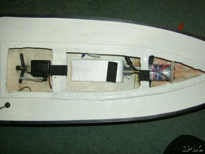
THE ELECTRIC STUFF I had read that 'electronics don't like to get wet', (try using your HiFi at the bottom of the sea) but on the boat's instructions doesn't make it very waterproof. I bought an airtight Tupperware type box (about 90 x 130mm) for use as a watertight radio box. The problem with these boxes is that no glue in the world seems to stick to them apart from Evostick (and that get quite unsightly). If you know of better glue, I would be interested to know. Due to the boat's internal layout the rudder post comes right up into the middle of the radio box! With a lot of jiggling around I got the rudder post, radio gear and the mechanical speed controller all inside the radio box! I couldn't find room for the radio batteries so they got stuck on the lid using 'Velcro' and Evostick, but this turned out to be a bad idea as you will see later. The deck opening had to be opened out to accommodate the box and top hatch also had to widened with Plasticard so it covers the radio box down to deck level.
As I couldn't get anything to stick to the plastic box I made up an internal platform from a sheet of 3mm marine ply or Perspex. Holes for the servos, speed controller and rudder post are cut into the ply and the whole lot sits on a couple of supports in the corners. . The platform is The whole lot then just sits loose on the bottom of the box, it can't move around because your plate just touches each side of the box.
I used a Tamiya mechanical speed controller activated by a normal servo (see BOAT ELECTRICS AND A LITTLE BIT MORE. ). This is a though unit and has withstood several 'burn-ups' due to weeded-up propellers etc. Resistive controllers can get very hot so leave a clearance gap around the coil so that it doesn't melt anything nearby. Lubricate the controller with silicon grease to inhibit arcing. The controller was fixed to the servo side with double sided tape. The action of servo this tends to push the controller off after a while so use a plastic cable tie to hold the two together. The cables to the battery connector and motor were run out of the front of the box through a rubber grommet and sealed with Evostick and a blob of silicon sealant.
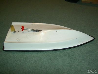
BUILDING SITE Because I was using a proper Huco type coupling The propshaft needed shortening. Push the bearing out and refit it to the now shorter stuffing tube. Remember to keep the same overall length from the motor to propeller.
After cutting everything else out or to size the first gluing job is the most important, the alignment of motor, motor bulkhead, coupling and propshaft. You'll find that I'll keep emphasizing the importance of motor alignment as a lot of beginners boats suffer from bad alignment and they wonder why the boat are slow, the batteries don't last and they are very noisy! POOR ALIGNMENT ROBS BOATS OF SPEED.
Cut a small pilot hole for the propshaft and open it out wide enough to accommodate the stuffing tube constantly checking it's actually in the right place in relation to the motor and rudder. Use a straight centre section for the Huco coupling while building which makes alignment much easier, replace it with the universal joint when the boat is complete. Dry fit the bits together and turn the propshaft over with you fingers and the only resistance you should feel is the motor. Don't oil the shaft, if any oil gets on the GRP the resin will not stick. Hold everything in place with sticky tape or clamps when done.
I found a way to check motor alignment is to run a low voltage, say 2 volts, into the motor. Measuring the current drawn by the motor with a meter, best alignment corresponds to the lowest amp reading. The motor only needs to turn over slowly so don't test your main cell packs on it! The movement will also help with cylindrical alignment too.
By the way, the motor, shaft and propeller needs to spin anti-clockwise looking from the back. If your motor runs the wrong way when you push the stick forward then flick the servo reverser on the transmitter or reverse the wires to the motor.
Once truly happy with the alignment you can pour resin over the motor bulkhead and shaft exit to fix them in place. The advantage of using resin here is nothing needs to be touched or moved. The shaft may need to be sealed to the outside of the hull with Bluetack or Sellotape to prevent seepage.
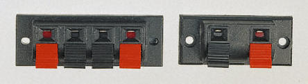
Once the resin has set the ply reinforcing wedge can be glued in under the inboard end of the shaft. I have since found out that this is a little unconventional and most boats, both real and model have a shaft support or skeg outboard near the propeller which helps damp down propeller vibrations and aid directional control. Holes for the motor and battery wires are drilled into the radio box and both bulkheads. All the wiring needs to be completed before the deck is fitted because it's impossible afterwards. The hatch spring clips are also fitted to the deck while it's still loose. When fitting the clips, use washers on the bolts to strengthen the deck else they could pull right through if you're not to careful. You won't want your new boat to sink so cut some polystyrene to fit in all the unused available gaps and the lid. If the boat now turns over and fills with water, it won't sink.
Next job, fitting the deck. Sand down the deck until it's a near perfect fit to the hull. Seal the joint on the outside with Sellotape or Bluetack to prevent seepage. Mix up some resin in small amounts and run it in through the three deck openings and then move the boat around so that the resin flows around the joint on the inside and on to the bulkheads. Do this a couple of times until the joint is completely bonded and you're happy with the seal. I added a little more resin to the nose to strengthen it in case of a head-on crash. You can check the joint with one of those angled inspection mirrors like your dentist uses before he starts to inflict pain! Stand the boat upside down and leave the resin to set overnight and sand the joint to perfect finish.
The radio box and radio etc. can now be fitted. Install all the radio gear into the box and connect up all the link and wires and oil the shafts. Test everything works correctly and smoothly, the more time you take getting this right now will mean more time on the water. If the rudder movement is reversed then again likewise flick the servo reverser on the Tx. If you transmitter has no servo reverser switch ask someone to fit one (a twenty minute job & about £1.50 for the switch, see BOAT ELECTRICS AND A LITTLE BIT MORE! or Radio Controlled Model Boats Magazine May/June 1990).
FINISHED? Lastly the hatch needs to be strengthened to take the force of you pulling on the dowel. Cut out a scrap of ply and make a 6mm hole to take the dowel, line everything up, superstructure, clips, dowel and supports, mark it up and glue the dowel and supports to the top with Superglue (fig c). Now you can fit the rubbing strip using Superglue, it also hides the dodgy joint you may have made! I didn't like an empty cockpit so covered it with a windscreen made from a scrap of theatrical lighting gel and stuck it on with Superglue. A good paint job and any other additions you can make to the appearance can only be an improvement to it in my personal opinion. Total construction time took me about 40-60 hours, sticking GRP together with resin is a job best not rushed.
So to the Water I filled the bathroom test tank and put in my new pride and joy.... IT DIDN'T SINK! This is a good sign. It floated with the water about halfway up the sides with a slight nose up attitude. I checked the radio and motor, everything seemed to be in order. So after a short run I wiped up all the water splashed everywhere and waited for the weekend.
The lady wife and all 7ft of my good friend Jason came down the lake one evening in summer '88 for the launching ceremony. I understand the usual pre-launch count-down procedure is to put one hand on your empty wallet, salute the sunset and say "I name this model ...... May she never sink, well not today anyway!"
I don't know what I really expected, maybe it would scream across the lake at a phenomenal speed or would it just move slowly around in pathetic circles. Anyway I installed all the batteries, tested the radio again and put the boat on the water and pushed the throttle stick gingerly forwards. IT WORKS! The boat moved off at a fair pace and was off ploughing through the water. It didn't scream across the water but I wasn't disappointed it worked. Speed was good, well I though so but I didn't have another boat to compare it against. I was disappointed the batteries only lasted what seemed a few minutes. Shame! I'll have to do something about that.
It's a very stable runner and can turn very tight corners without complaint. At full speed, full rudder can be applied and I couldn't turn it over but it's not recommended for mental stress reasons. At slow speed it can turn in about two boat lengths but I did give the rudder a lot of movement. Trying to run astern pulls the stern under and floods the deck.
PROBLEMS The first thing to go wrong was the coupling supplied with the kit. It exploded when the boat came to close to shore and the prop run aground. A Huco / Ripmax coupling was then installed ( see above ). The replacement coupling has withstood some serious misuse without any sign of distress. The brass rudder blade did come loose a couple of times when the boat was in shallow water but this was easily re-soldered.
A second problem soon showed up. After a short run the main cells would loose power for no apparent reason, even while on the bank and the radio switched off. This turned out to be a combination of a few things,
1. The mechanical speed controller is not a piece of precision engineering and the 'backlash' is quite noticeable on the wiper arm.
2. The wiper arm by design has to rub on the coil resister with quite some force to ensure good contact.
3. Servos don't like metal to metal touching as this causes radio interference thus making the servos twitch.
The upshot of all of this is that the servo doesn't move the wiper arm to dead centre of the resister every time (which cuts the circuit) and thus part of the resister remains in the circuit and causes the cells to discharge. I fitted a power switch between the cells and controller - not knowing any better at the time. On my model, I combined the power and radio cells together in one 2 pole- 2 way switch. If you don't know about switches ask someone in your local boat club to help you.
Batteries The Piranha is quite fast on 8 cells but runs much better on 10 and gets upon the plain in a couple of boat lengths. In order to save money on the main batteries I opted to buy eight individual rechargeable cells ( D cell torch type) and connect them a via spring type battery box, but this was given up as a bad job after the a particularly unsuccessful voyage. I hit a turn buoy and the cells were not knocked loose from the holder which left me with a dead boat with not the slightest breeze on the water. I tried throwing stones just pass the boat in the hope that the ripples would persuade the boat back in. This is not a good idea. Yes, the boat took a direct hit from a very hard flying bomb. My wife asked me 'why was I trying to sink my new boat?' After several hours it drifted in on it's own and I was pleased to see the only damage done was to crack the gel coat surface. I decided to make up cell packs and discard the battery box idea.
I got hold of some cheap second-hand NiCad cells from a model shop, most of which were good. These cells I made up into sets of five by soldering them together with brass strip, two pick-up wires and covering them with heat shrink plastic. Two packs are used at a time which takes the total voltage up to 12v. I then fitted Hi-fi speaker wire connectors available from electronic component outlets like Tandy, Maplin etc. These are used to quickly connect up the home made battery packs which I made less the standard model battery connectors. This left me with fully charged batteries with bare wires!!!! - This is not a good idea!!! Spend the extra money and get good batteries and use proper connectors. |
|
|
|
|
|
. Sticking the radio batteries ( also individual batteries in a spring type holder ) on top of the radio box was also a bad idea as it kept getting in the way and the holder split twice and had to be replaced. Soon the batteries became corroded and also had to be replaced. It's better to get them in the radio box if at all possible and use a proper soldered receiver pack.
Once I was happy with the mechanics and running of the boat I started on the quest for more speed. Changes of propeller increases speed but the larger the prop the shorter the running time, 35X to 40X is the best range. The original motor was a bog standard 550, I then tried a racing type 540 motor, a SPRINT 12 but the motor didn't seem to have enough torque and performance. After a few runs the SPRINT was removed and the 550 refitted. A more powerful motor and/or batteries would take the hull nearer it's full potential. I never got the boat anywhere near instability so I imagine it could have taken quite a bit more power than I ever used. But as this was my first boat I didn't know how to get it to go faster with putting more cells in or a bigger motor, (more of this problem in another page).
RESCUE ONE This boat has proved very useful in later days as tug for my dead IC boats. The idea came to me when my next boat the SHADOW, stalled on a very cold winters day in the middle of the lake and it wouldn't drift in. I fitted a bollard (a plastic screw) in the deck at the transom, attached a line of about 3 or 4 meters and a small float at the end. The line is trailed out behind the boat and the boat made to circle a dead boat on the water. Once the line snags on the propeller or rudder, I circle the boat a couple of times to make sure it's secure and then tow the dead boat in backwards. It works a treat. It's pulled in dozens of dead boats on the Osier Lake in Peterborough, some of them quite large. Only thing though is be careful not to snag your own boats propeller on the line by going backwards or you'll have two dead boats on the water. That's when it usually starts to rain...
CONCLUSION The PIRANHA is a good boat to learn about model boat building, maybe a little too much, but not an impossible kit for the first time modeller. If you want to learn all about GRP electric boats then this is the kit for you but starting in ABS is easier and quicker. As it's style gives away it's age but you could always build your own. One last thing If building the Piranha, build it as light as possible, I've seen one built better than mine and it was and it ran very well. EPILOGUE The Piranha has earned an honorary retirement now and was replaced by a semi-scale tug the ORTON built from a ONTARIO kit (to be covered in another page). I will always have fond affection for this boat as I learnt so much about the many different aspects of boat modelling. I've had hours of running time with this boat and I did succeed in building a working model boat and it's a great feeling to see something you built, work. I'm sorry there are no on the water pictures but I didn't know I was going to do this web site before retiring her - to the bin. Sad end but that's life!
LESSONS LEARNED 1. Make sure the first boat you build is an easy build or you could quickly become despondent, disheartened, bored etc.
2. Resistive coil speed controllers need a eye kept on them all the time as they prone to burning up and draining your cells. On a next boat I'll try a different type of controller.
3. Size does matter.. a small one give longer performance, larger ones goes faster but not as long.... I'm talking about the Propeller!!
4. Check the radio gear frequently, and strip down the gear from time to time to check for water getting in. Make sure the prop shaft is well lubricated, install an oiling tube.
5. Build 'getability'.
|
|
|
550 motor 35X - 40 propeller Tamiya resistive speed controller 10 cells (12v) Accoms 2 channel radio External power + radio switch |
|
|
Higher powered motor Gear box Surface drive Extra cells Metal propellers IC conversion! Appearance! |
|
|
Value ........................... Kit Quality ................... Kit Design .................. Ease of Building .............. Finished appearance ...... Handling ................. |
8 (Very reasonable)
|
|
The PIRANHA never turned over or sank which is more than I can say for my next boat, a SHG SHADOW. I now wanted to build a faster boat and one powered with a IC engine. The most complete IC kit on the market that I could find was the SHG SHADOW. I bought one and smuggled it into the house late one after the Mrs had gone to bed.
Well all of this
is just my opinion, but what do I know! |
|
|
|
|
|
|
|
|
|
|