| John Richardson - "Free Lancer" | ||||||||||
| Having completed a major opus, a traction engine which took 6 years, I had been looking for a new project to occupy my time and give me something to think about in otherwise dull times such as when shopping, dishwashing and all the other similar chores. | ||||||||||
|
|
||||||||||
|
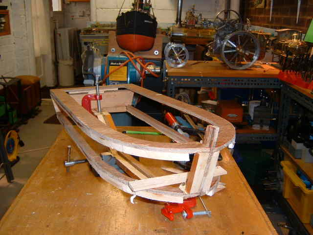
The present fleet of boats includes two sailing cruisers, a Rhine pusher, a fast launch, a Puffer and a crash tender so a workboat offers the variety necessary to add interest. Freelancing would also add to the fun as it would entail searching the web for interesting layout and detail. Size is to match that of the Pusher, Puffer and launch such that they can all be accommodated in the car boot. ( I decided not to build the 'Civitaveccia ' www.scalemodelboatyard.co.uk having had nil response from various authorities in the port of Civitaveccia, Near Rome, to a request for details. Too busy I suppose.) I regard it a challenge to build mainly from scrap, except for the electrics and electronics, so the hunt was on for ply and timber. The older the timber the more likely it is to be knot-free and of general good quality, superior to stock in the local DIY store ! Post WW2 ply is generally WBP (Simply tested by a good soaking ) and anyway all will be protected by paint or varnish coatings. So the boat will be all wood and the design from my wooden head. No doubt we have all read a book on our particular interests entitled ' Coarse Rugby '...or something similar, my piece that follows could well be entitled ' Coarse Model Boat Building ' as it describes my, sometimes oblique, approach to model making. To add to the interest of the build a different construction method will be used to ensure ' Bags ' of space inside the hull, uninhibited by bulkheads, Simple keel, bulwark and chine formers have been laminated from ply and timber and set-up using suitably sized spacers to provide the hull form. |
||||||||||
|
|
||||||||||
|
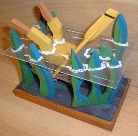
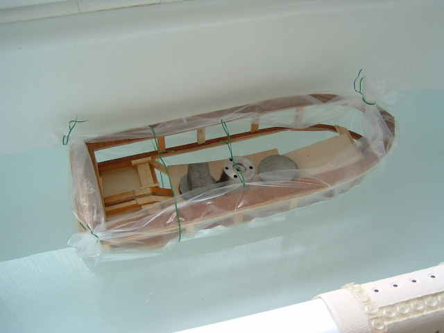
One or two additional timbers are required to provide a seating for the skin and to generate the rounded stern, these can be removed later as the skin provides the structural strength. PVA adhesive will be used throughout as it is protected by coating later. Brass pins are used to secure the sheeting and the occasional wooden dowel employed where a pin would otherwise be difficult to insert, The superstructure will be kept as light in weight as possible. The seemingly over wide bulwark frame is such that coamings can be fixed to it to provide the water bar at the base of the superstructure. Deck camber will be introduced using profiled splints of 1.5mm ply. One or two additional timbers are required to generate the rounded stern. As the hull took shape, the centre-of-gravity of the structure could be established simply enough but it is helpful with a new hull to know where the centre-of-bouyancy will be, and what are the chances with a freelance design that, with batteries and gear installed, it can be made to float at the intended waterline. To establish this the hull was ' Gift wrapped ' in stout plastic sheeting and given a ' Bath test ', weights being added to simulate that of the superstructure, motors etc. |
||||||||||
|
|
||||||||||
|
The result of the ' Bath test ' on the gift wrapped hull showed that the intended waterline could be achieved later, and the material in the stern-works would cause no problem weight wise. With 7lbs plus of weight onboard the shell settled to 1/2" below the intended waterline so plenty of scope for a gel battery, sited low in the ' guts ' of the boat, also motors, controls and superstructure. |
||||||||||
|
|
||||||||||
|
The structural frame with its temporary supports proved sufficiently rigid to allow fairing-off using a power planer, set to a very fine cut...so much less hard work than rasp and hand plane. Anyone who has built a full-size dinghy will know how much work fairing-off means there ! The power planer was long enough to span the profiles and thus cut the ' lands ' for the ply sheathing at the correct angle to allow the 1.5mm ply skin to bed down properly. Care was needed however, to ensure that the planer didn't gobble-up the structural members ! |
||||||||||
|
|
||||||||||
| Whilst 4mm ply was used for the under stern sheeting which is to support rudder posts and propeller shafts 1.5mm ply proved sufficiently rigid for the hull in general when supported at the bulwark and chine profiles, even where there is a lack of curvature to stiffen it. The bottom panels were pinned briefly and the overall shape traced for the first rough cut. My 40 year old band saw, with metal cutting blade simply eats the stuff and leaves a smooth edge without ply breakout. PVA adhesive is liberally applied and the pins are driven in, working from stern to bow, ensuring that the ply is fully seated on the formers. Where necessary a hunk of metal provides a ‘ strong back ‘ such that the pin takes all the driving force and the frame does not suffer shock. Pins can be punched-in later. | ||||||||||
|
|
||||||||||
|
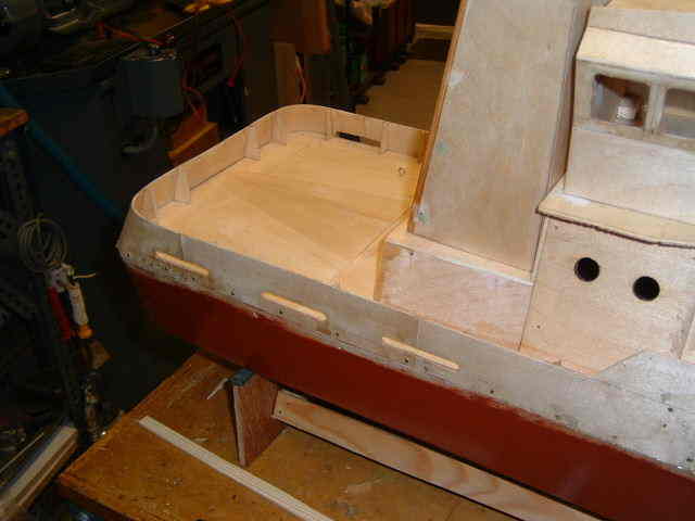
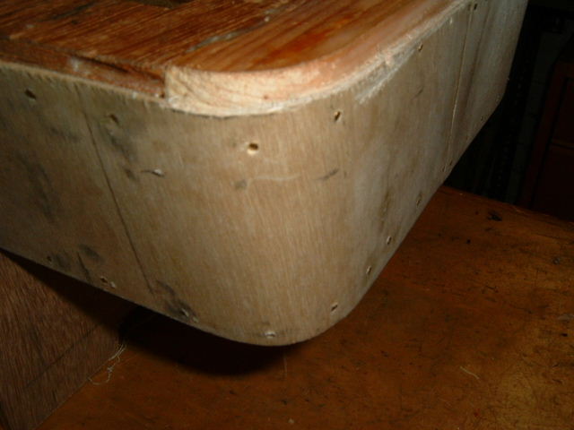
Not a lot to be said about the hull side sheeting, although, it has to be said that the process was started, not at the stern but about 60mm for’ard of the curved stern-quarter formers. Coating the frames with adhesive followed by progressive pinning whilst clamping and pressing the skin to the profile formers ensured a good seating. Timing was of the essence here , so the glue coating was applied part along the profiles and completed as the fixings moved for'ard. With the sides of the hull sheeted, attention turned to the stern, with its rounded quarters. The combination of flair and curve with use of ply off cuts resulted in the need for a gusset piece to be inserted centrally at the stern. It is not a good plan to attempt to lay on curved sheeting starting at the tangent point...better to first lay some flat sheeting then pull the ply around the curve pinning or clamping as one goes. This ensures a smooth transition from flat to radiussed form. The sheeting should continue on past the curve for the same reason. It all looks quite rough in the illustration but sanding and filling are to follow ! |
||||||||||
|
|
||||||||||
|
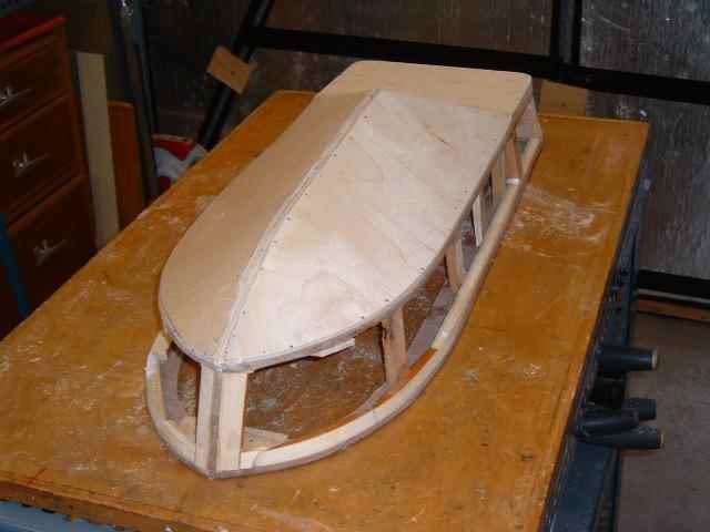
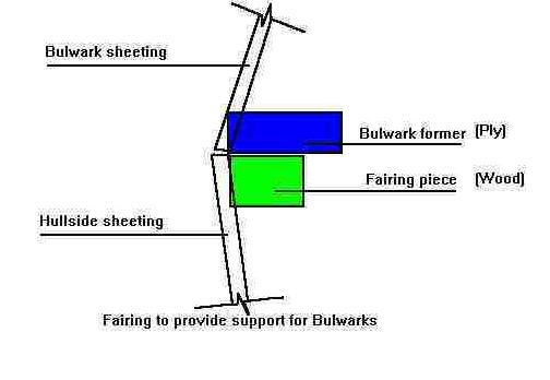
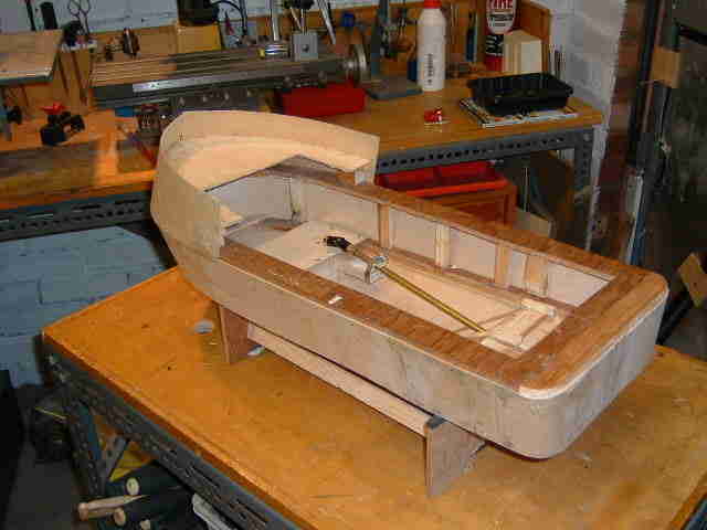
Using this method of generating the hull form, there is a huge amount of space for battery, motor and electronics. The absence of bulkheads offsets the weight of the profile formers which are of 6mm ply, plus the fairing pieces which are laminated onto them to provide lands for the sheeting. The bow and stern bulwarks on most boats of this type have pronounced tumblehome and the means of supporting these items on Freelance is illustrated in the sketch herewith. Of course the joint will be planed later to provide a seating for fender strips. |
||||||||||
|
|
||||||||||
|
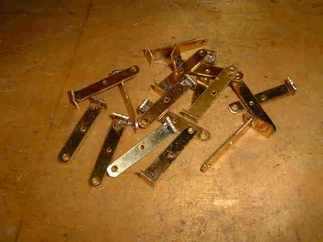
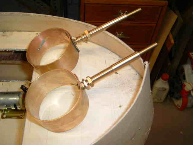
The bow bulwark took a lot of effort to ensure that it seated onto the profile at the bulwark and onto the foredeck which had been mounted on blocks at the required angle. The curvature ensures the strength to withstand later bumps and it is intended to fit a forward push post. At this stage it was time for some small engineering works The rudders and nozzles on my Rhine ' Pusher ' give excellent steering control and considering that the materials came from the scrapbox, cost little besides my time ( At my age of 76, unfortunately a wasting asset! ) So to the lathe and bandsaw. I used 1/16" brass to make the fittings just that bit beefier than those on the Pusher. The nozzle, was formed round a piece if scaffold tube then rivetted. The post was turned from brass and a 5/16" M.E. Thread cut to take the nuts securing it to the hull.....time 45 minutes in all. The posts are 3/16" brass with a 3/16" threaded portion to engage with the nozzle. The rudder blades are soldered into place. Soft soldering has sufficed on the pusher for 2 years of hard usage and was considered OK here. No Lloyds Certificate perhaps but sufficiently durable for my purpose ! |
||||||||||
|
|
||||||||||
| The propeller shafts. universals and propellers are commercial products from my local friendly model shop ' Wycombe Models '. The fixing is unorthodox, hose clips secure the tubes to posts which run each side if the eventual battery position. these allow for easy adjustment until all is lined up correctly when a dose of Cyano will ensure that nothing moves ( ever again ! ) | ||||||||||
|
|
||||||||||
|
The work ( or play ) described to this point has taken something of the order of 40 hours. The cost to date something like £30. Estimated final cost will be less than £100. The build has been carried on in odd hours snatched from my otherwise very domesticated life. |
||||||||||
|
|
||||||||||
|
I see this as pretty good value in terms of
entertainment, and an excellent investment when I look forward to the
hours of enjoyment my young relatives and I will take from the finished
article.............................. |
||||||||||
|
Continuing the build of the workboat now renamed ' Free Lancer ' at 20th
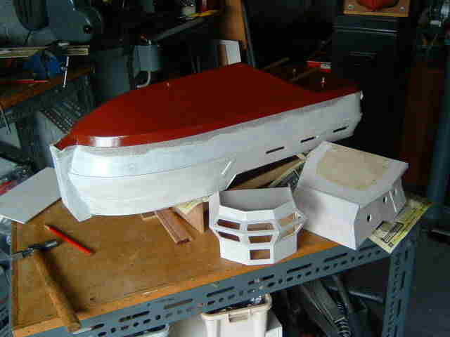
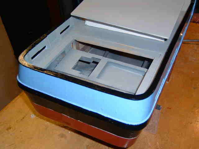
August 120 Hours and counting, I have to complete the decking leaving a substantial hatch in the after deck for access to the steering gear, radio, BEC and so on, The hull has had 2 coats of varnish as a seal and then 2 coats of red primer. Later the approximate waterline will be completed using the usual pencil and set square dodge. With the approximate water
line established it was time to cut the freeing ports using a minidrill
with dental burrs donated by my dentist, great stuff, miniature diamond
coated milling cutters eat plywood ! Trouble is that they tend to run
away, and need a firm hand ! |
||||||||||
|
|
||||||||||
|
|
||||||||||
|
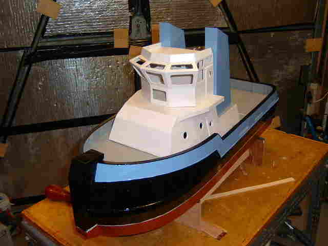
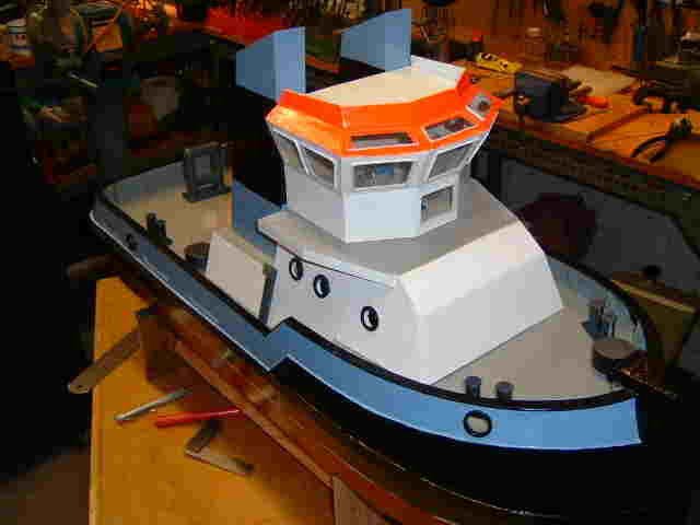
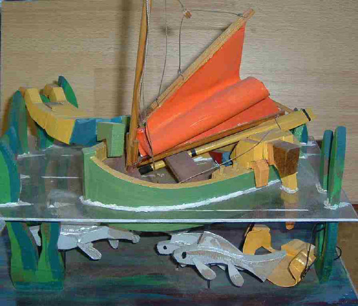
A colour scheme is emerging ! The waterline has yet to be finally established, hence the white strip. The reflected light in the image does not do justice to the ' cutting in ' between colours, A coat of matt varnish will improve the overall appearance later. It wiull also be neecessary to decide on the final appearance, pristine new or weathered in service !. |
||||||||||
|
Controls and some instruments also the Skipper and First Mate have been installed in the wheelhouse. The bollards and part of the towgear have been fabricated, sprayed are now set in place on deck. Hawse holes have been turned up on the lathe and set into the bulwarks. Thanks be for the dental burrs ! |
||||||||||
|
|
||||||||||
|
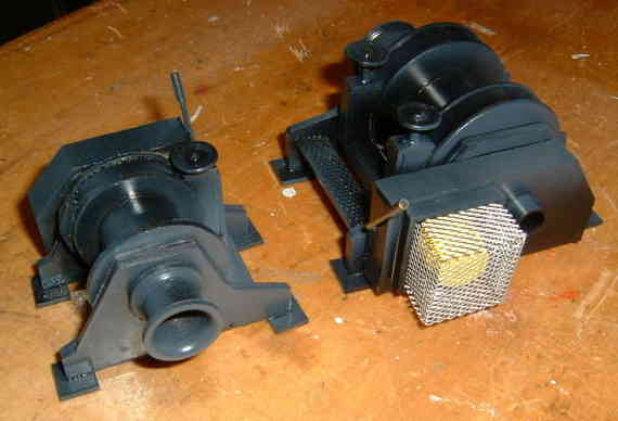
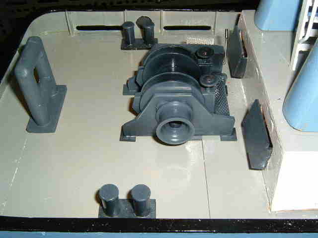
135 Hours and counting. The
next job will be to insert the props, nozzles and install the twin motors.
OK so in need of a change I started on a different tack ! Controls and some instruments also the Skipper and First Mate have been installed in the wheelhouse. The bollards and part of the towgear have been fabricated, sprayed are now set in place on deck. Hawse holes have been turned up on the lathe and set into the bulwarks. Thanks be for the dental burrs ! A solid joint piece has been turned up on the lathe to substitute for the universal joints when lining up the motors with the prop shafts 135 Hours and counting. The next job will be to insert the props, nozzles and install the twin motors. OK so I needed a change. I |
||||||||||
|
|
||||||||||
|
|
||||||||||
|
|
||||||||||
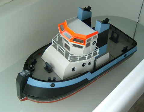
|
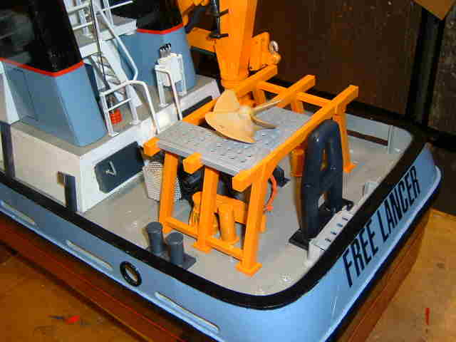
Now at 150 hours into the build the boat is taking on the appearance that I envisaged when I started out early in July. It is a mix of many of the features that I enjoy when looking at the real thing and if nothing else it has character ! Motors have still to be installed using a solid connection during fixing in place of the eventual universal joint. This to line motor and shaft, critical to vibration free running, This is an idea gleaned from Martin. Webmaster and owner at www.modelboatmayhem.co.uk a site that I visit frequently and where Martin kindly exhibits models made by many people ( many more skilled than me, but few making freelanced vessels built from scratch and scrap such as Free Lancer ) Next......... two winches and a crane, also emergency equipment, hatches etc. then the radio, BEC, servo etc. plenty of work to ' keep me out of mischief ' |
||||||||||
|
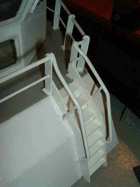
Took time
out to construct the access steps to the wheelhouse deck, |
||||||||||
|
Next......... two winches and a crane, also emergency equipment, hatches
etc. |
||||||||||
|
|
||||||||||
|
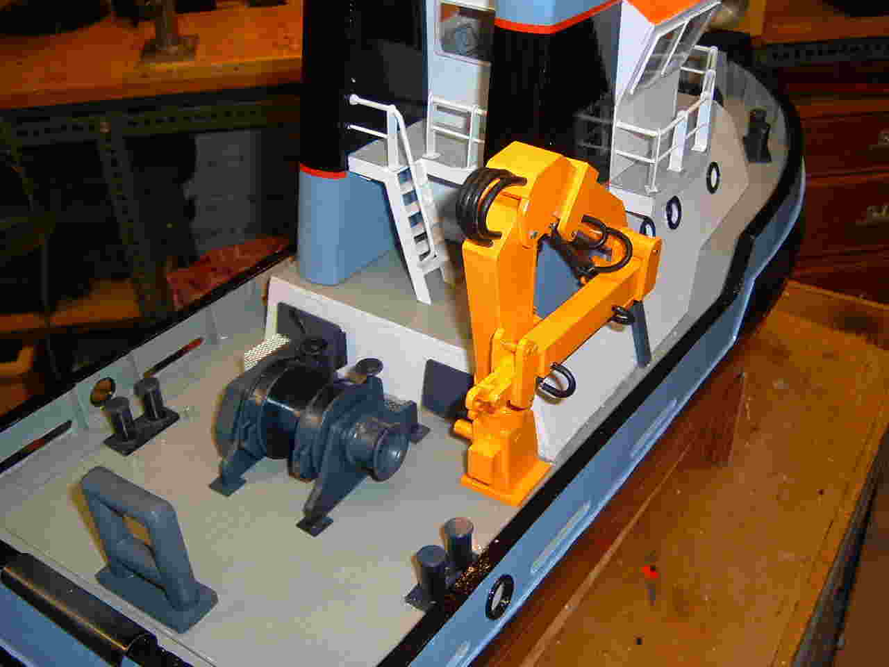
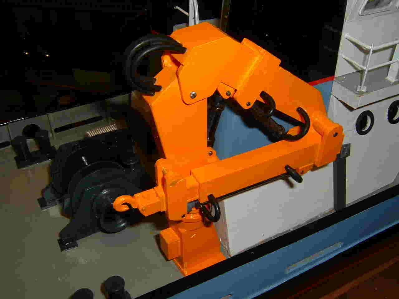
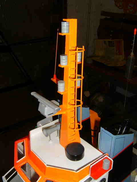
Now for some more plastic fun, building a convincing looking crane. I don't like making non-working items but a working crane would be too demanding on my spare time. I have seen a few illustrated in Model Boat Magazine and applaud their makers efforts.....not for me however ! 192 Hours and we have a crane ! The last 25 hours of sporadic work, carried out between domestic duties have resulted in a crane that I am quite pleased with. One's own product is not always pleasing and sometimes exhibits, to the builder at least, the defects that he knows are built-in. OK so I know where are the defects in this latest addition to the boat, but I can live with them ! |
||||||||||
|
|
||||||||||
|
The crane is secured using a 7BA stud cyano-ed (Super glued) into the crane standard, taken down through the deck where an oversize washer and nut secure it against rough handing in service. The crane like the funnels and the superstructure can be removed in the event of work being required on the hull. |
||||||||||
|
I must admit that at some tricky stages in the crane construction I thought wistfully of the folk who open the box and,,,,,,,,,, there are the parts all ready for assembly ! But, as the job neared completion well into the 25 hours of scribing, cutting, filing, bonding, turning, tapping, bending, tapping, painting and fitting I found consolation in the saying ' You're an ugly little devil but you're mine, all mine ! ' Access ladders, mast, radars, hatches and so on next, then installation of radio, BEC, motors etc. plenty yet to go at.! |
||||||||||
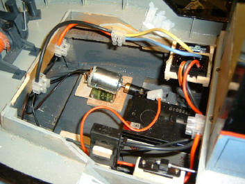
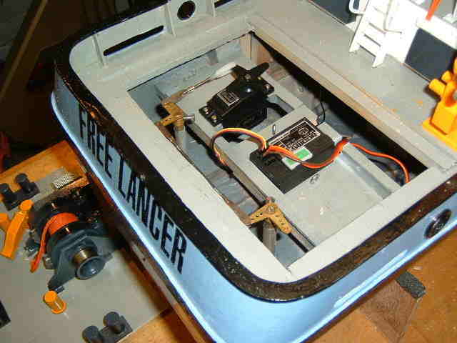
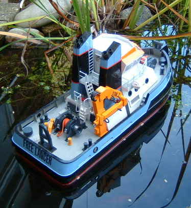
On a more serious note, It wa time to complete the controls on ' Free Lancer '
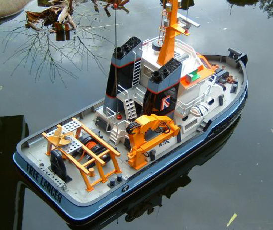
It was pleasing to find that with all the gear installed, and little other than mast, lights various radars and rails to the wheelhouse deckhead to be installed, that the boat floated level (and with a little added lead well down in the bowels ) to the previously marked waterline. 230 Hours in and with the controls installed came the moment of truth, the big switch on. I have installed an MSonics Mariner 15 Bec with an inline fuse and as usual 2 Como 380 motors. The motors are run in parallel, .......................no need with steerable nozzle/rudders for independent speed control. The radio is 2 channel AM Acoms It is intended to supplement the two channels with a multiswitch at a later date. to facilitate sound effects. So that is it for now, I will come back to the ' Free Lancer ' page when I test it on the local water. Meanwhile here are a couple of shots of the near finished article.
|
||||||||||
|
252 Hours into build, I have trimmed boat on my home
pond using plumbers lead sheeting cut into tiny squares and ' bagged 'for
location, it will eventually be fixed in position permanently with
plaster. I have also realigned the motors and cleaned out the propellor tubes as drag caused a couple of fuses to blow. Thank goodness for the recommendation in Model Boat Magazine regarding fuses. It saved me a major problem when, in the dusk, I inserted the battery wrong way round, polarity wise....which could have cost me an electronic speed controller! The mast has taken shape, it sits on a wooden post and can be removed and replaced by a shorter version if the ' windage ' is too great in bad weather.
Now there is the tidying up to do, Touching up the paint job etc. I still haven;'t decided whether to ' Weather 'the paint to give that ' In service ' appearance, at least I will spray down with matt varnish to take the gloss off everthing, Whoever saw a workboat in pristine condition ? November 16th ( 260 Construction hours to date ) and still adding detail.,
Also since the last update I have been adding ballast, well down in the hull to stabilise the boat as well as sealing the after hatch (access to the radio and stern gear) using a silicone paste. The latter to prevent taking in water in bad weather. A few final details to add,
then it will be time to consider the next project. |
||||||||||
|
Thanks for visiting the build !
Very best wishes, |
||||||||||


.JPG)

.JPG)
.JPG)
.JPG)
.JPG)
.JPG)