|
John Richardson's - "Free Lancer II" |
||||||||
|
Johns
Model Madness |
||||||||
|
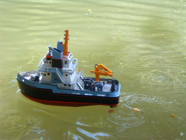
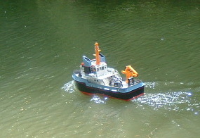
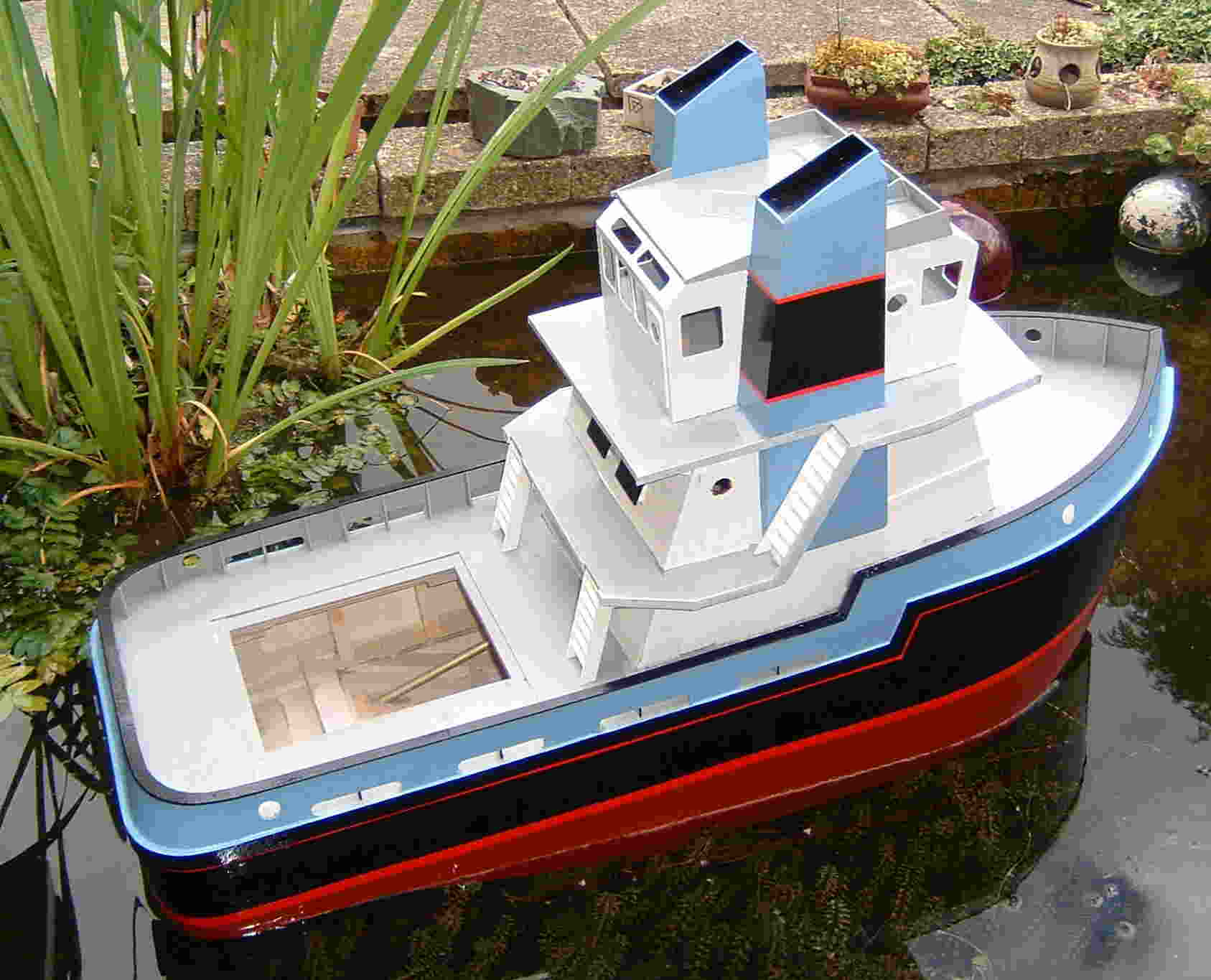
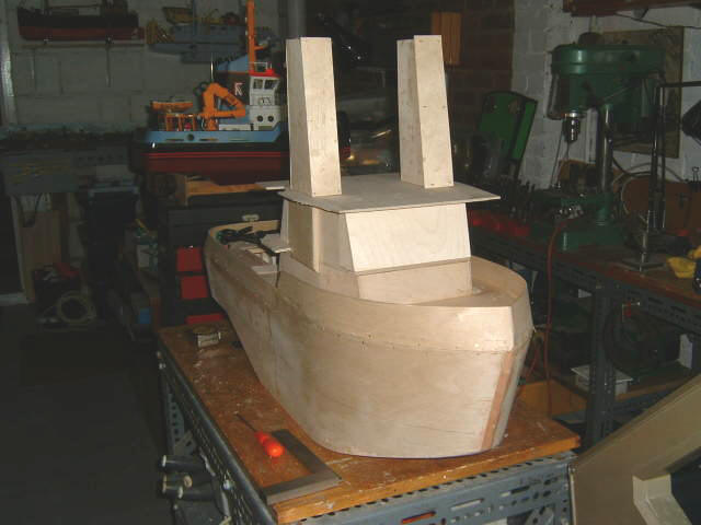
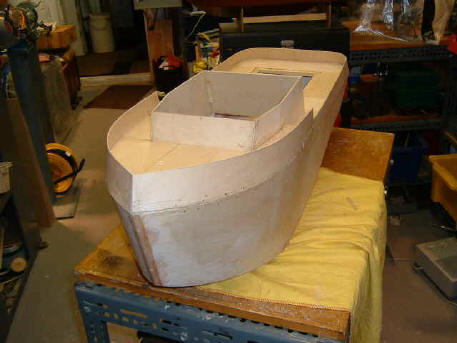
Free Lancer 2 ' ' redesigned ' Trials on the local water indicated that whilst Free Lancer 2 motored and responded to the helm well , on a tight turn the heel was more than we liked. OK so all ( Most ) boats heel to a degree and whilst Free Lancer recovered., the heel was unrealistic The solution, very drastic was a ' Redesign 'involving taking a a panel saw to the model just below the bridge dack !..........resulting in lowering of the C. of G and losing more than a pound of ' Top hamper '. Railings, liferafts and ' etceteras 'were recovered This after using the computer to visualise the outcome of the surgery.
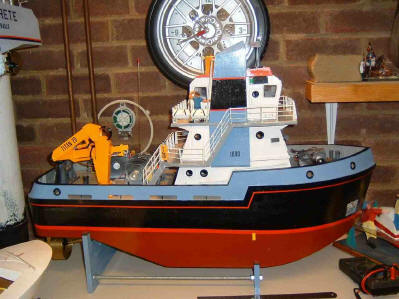
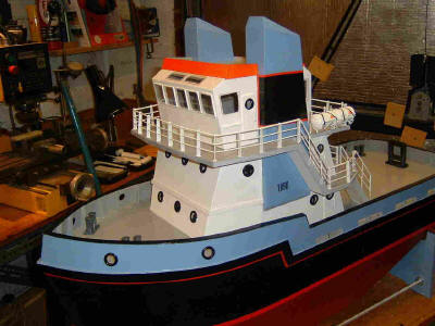
Freelancer 2. It has a good turn of speed, excellent manouverability, good wave form but excessive heel on turns, probably due to the wooden superstructure raising the C of G. I decided that action must be taken ! First I took a 'Broadside' view of the boat as existing. Apologies for the extraneous background....j'm just an amateur photographer you see !
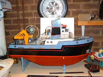
Using Microsoft ' Paint ' and took a copy of just the wheelhouse section. The next move was to paste the cut onto the last image .........to get an impression of the ' redesign ' Satisfied that the result would still convey the right image
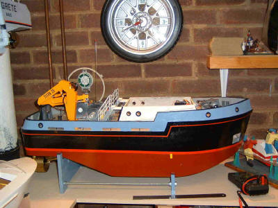
Then I sawed through then removed the superstructure just above the engine room level, that being a permanently attached to the hull.
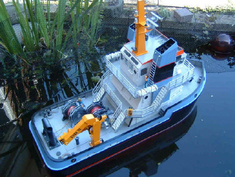
A few days and many hours later the remaining upper works have been tailored to fit the fixed part of the superstructure and the whole thing looks as if it were designed that way.........................a lesson learned and goodbye excessive heel !
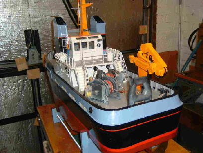
Here is the stern view of the revised boat with the wheelhouse lowered.....after all bits are sometimes added to boats..........so why shouldn't bits be removed ?
After modification, less heel on the turn.......the boat is far more stable altogether. The ' designer ' ( Me ) is pleased at last ! That really is the end of the ' Oddysy'..........Many thanks Martin at www.modelboatmayhem.co.uk for the ongoing support, and congratulations on the forums................a feast for model boat enthusiasts March 2007 Thanks for viewing the build.
|
||||||||
|
Free Lancer II revised Trials on the local water indicated that whilst Free Lancer 2 motored and responded to the helm well , on a tight turn the heel was more than we liked. OK so all ( Most ) boats heel to a degree and whilst Free Lancer recovered., we were not satisfied. The solution, very drastic was a ' Redesign 'involving a panel saw!..........lowering of the C. of G. Railings, life rafts and ' etceteras 'were recovered This after using the computer to visualise the outcome of the surgery.
I went to MSpaint and took a copy of the wheelhouse section
A few days and many hours later the remaining upper works have been tailored to fit the fixed part of the superstructure and the whole thing looks as if it were designed that way.........................a lesson learned and goodbye excessive heel !
That really is the end of the Odyssey...............Many thanks Martin for your ongoing support, and congratulations on the forums................a feast for model boat enthusiasts
|
||||||||
|
Part - The Last
Dear Martin Thank
you for your ongoing kindness and assistance regards and best wishes |
||||||||
|
Part - The Twelfth
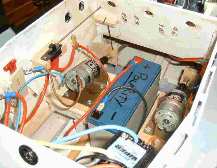
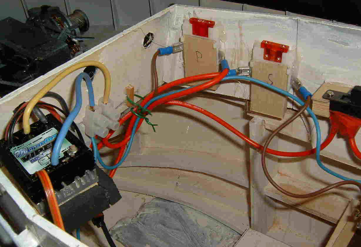
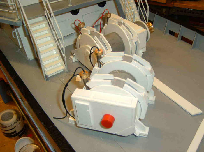
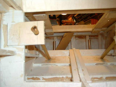
15th February, 279 hours into the build Sufficient electrics are now installed to run the boat. More will be installed later including a cooling fan for the engine room. There is plenty of room for additions although electrical connections to the removable superstructure from the hull have to be sorted out. I have in mind blade contacts similar to those on automobile fuses ( male and female bayonets )
The battery(s) are well below waterline to assist with stability, the ply superstructure presents a small problem here, being quite weighty compared with the styrene topsides featured in many kits.
Initial set up of the ESC was simple enough though I thought the instructions for setting up the delays could have been clearer. Fortunately I have a son who is of the generation that expects electronics to work, whereas I have to admit to belonging to the generation that expects them NOT to work, and he sorted me out ! After some instruction I have to admit that the instructions are correct though the illustrations are a little abstruse.
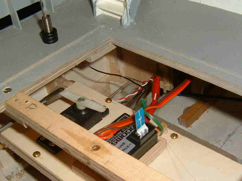
The antennae took some time to fix. Can't some enterprising person devise and market a base that can be connected to the radio lead PRIOR to insertion of the base into the deck. I worked using a mirror, how on earth do dentists work in a person's mouth when every movement is contrary to what is normally to be expected ! Final ballasting will follow plus accommodation for large or small batteries also a cooling fan for the engine department.
|
||||||||
|
Part - The Twelfth
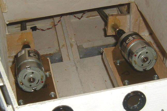
I contacted Paul Kenningly of Mtronriks via their web site and he advised
me that with my two Graupner 600's it would be best to use one of their
40c ESC's..... I will have to save my pocket money for a few weeks and
then I will follow his advice. Meanwhile I have to buy 2 of Halfords best
auto fuse holders, the RX, main switch etc. and install them. jobs not too
demanding even in the absence of training as an electrician. |
||||||||
|
Part - The Tenth & Eleventh
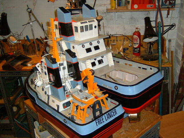
There is still space for a crane, or such is the nature of freelance construction, as this has developed into an offshore vessel, I might add a davit and a rescue boat. . |
||||||||
|
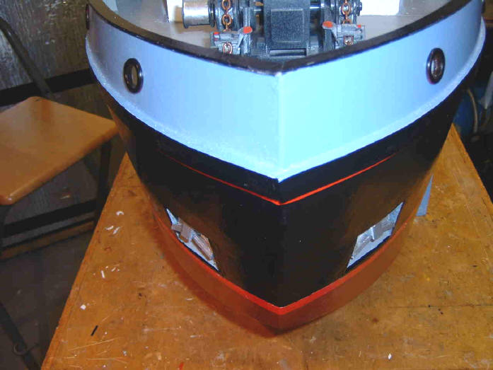
210 hrs into the build and we have cut into our precious hull and inserted anchor wells and anchors. OK, so the wells are on
the waterline but as we say there is a prototype for everything and ours
is on the ' Antwerp Harbour Tugboat site
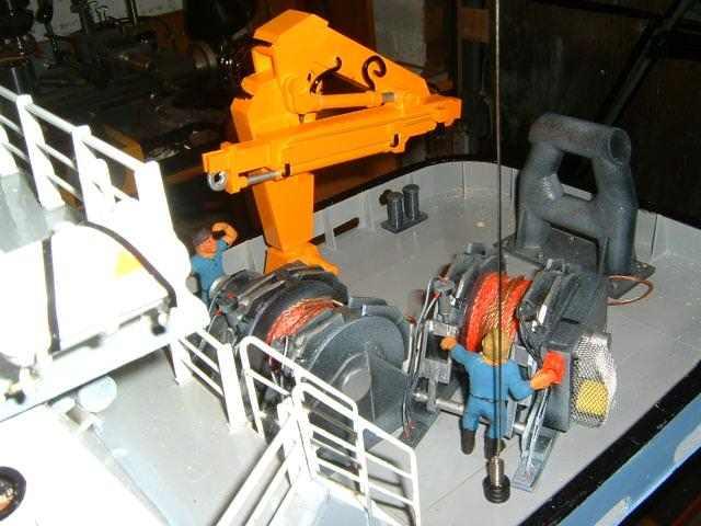
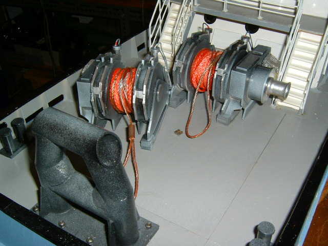
With the wells completed attention turns once more to the main winches, adding hydraulic piping and arranging their fixings to the removable hatch. The prototypes for the winches were also viewed on the Antwerp site...a haven for modellers seeking details from a landlocked situation !
The winches have taken a long time in production, delayed by three spells in hospital where the planning for future model activities was one of the few things preserving my sanity ! It's great to be back in the workshop and busy with the most important things in life again !
|
||||||||
|
Part - The Ninth
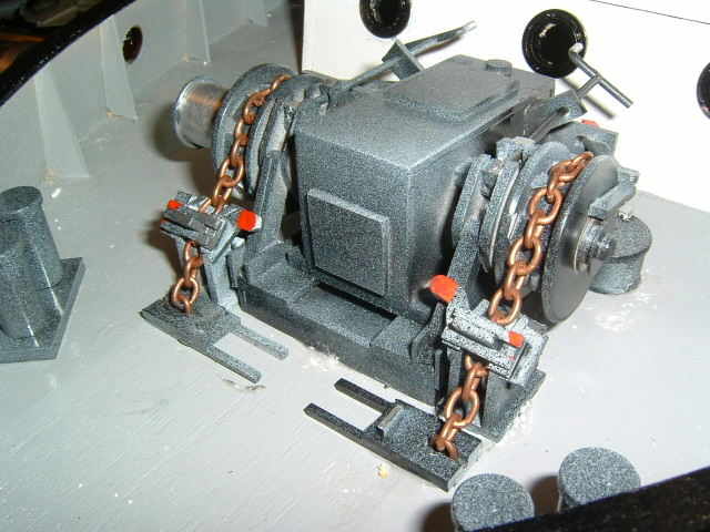
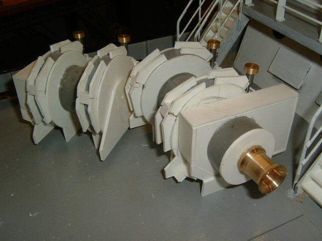
Work has started on the deck gear, mainly from plastic sheet with accessories turned from brass on the trusty Myford. The anchor winch is electric powered on the prototype ( Based on an Antwerp tugboat found on the web. The chain is not quite correct but serves to present the picture. Now that there is an anchor winch it will be necessary to butcher the bows of the hull for anchor stowage.
The Embrio main and
auxiliary winches are hydraulically powered, here
they are shown in the raw. The model shop must wonder where their stocks
of 2mm plastic sheet have gone !
|
||||||||
|
Part - The Eighth
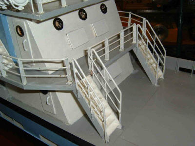
I am 170 Hours into the build of Free Lancer " and have spent some time on the rails and some lift rafts.
The rails are of 3/32" and 1/16 brass wire and the stanchions are from 1mm brass sheet ( mixture of measure ! )
Life rafts are from plastic electric conduit and 2mm plastic card, the stiffeners are slices of the conduit.
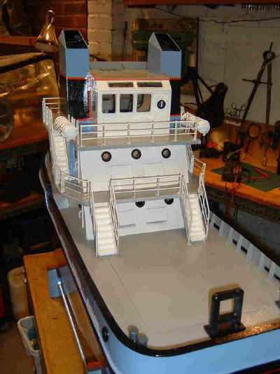
The steps to the stern deck are attached to the deck as the 2 upper decks of the superstructure are removable for access to ' The works ' The joy with free lance models is that details from many boats can be incorporated and the whole thing can be as the builder wishes, as long as it is realistic...so we can add bits on just as we wish ! That is the current stage of construction.....so much yet to be done and I haven't yet decided whether to go to 6 V or 12 V and what motors to use. 6 Volt with 2 jel batteries in parallel seems to be favourite as the cost of controllers is reasonable and it will provide a degree of interchangability with the gear in my other boats. The next section will deal
with the deck gear so it could be a while yet. |
||||||||
|
Part - The Seven
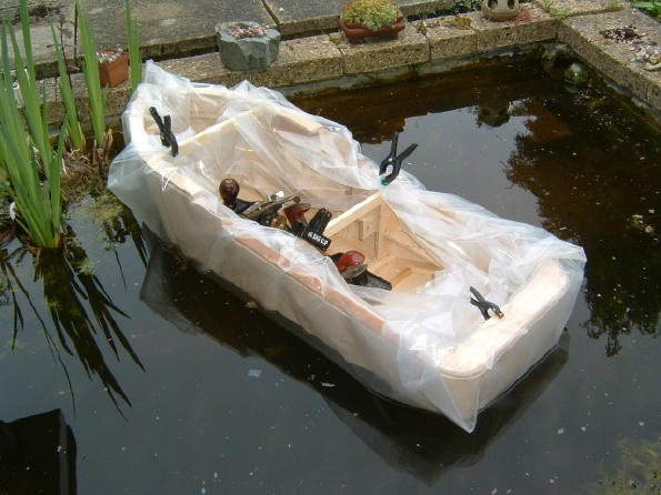
So at 120 hours into the build, fair progress has been made....many more hours of pleasure to come. Soon it will be back to the lathe to turn the 15 or so portholes. With the stern tubes
plugged and without ballast we hiked to the pond, took a deep breath and
in she went. The fish took a dim view but I was fairly pleased with the
launch......... no champagne ......just a cup of tea. Of course without
ballast she floats bow high, this can be simply adjusted.
The length is 850 mm, beam 275 mm and the draught 75 mm I am still open to
suggestions regarding suitable motors ( See my question ' Suitable motors
for.......' on the Model Boats Magazine, Scratchbuilding forum.) |
||||||||
|
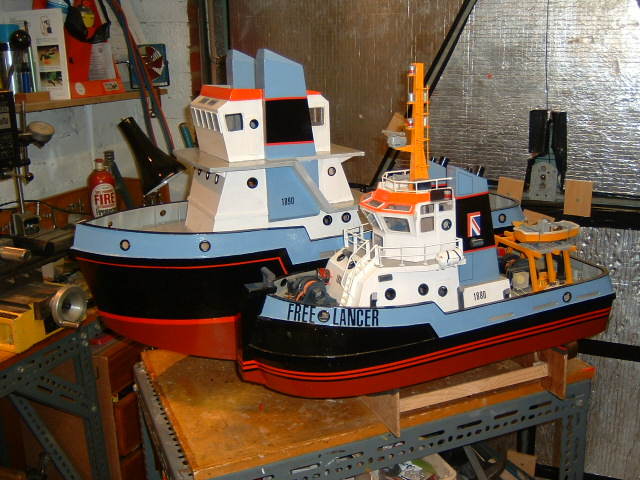
So to give an impression of
the size I have put the boats side by side.
|
||||||||
|
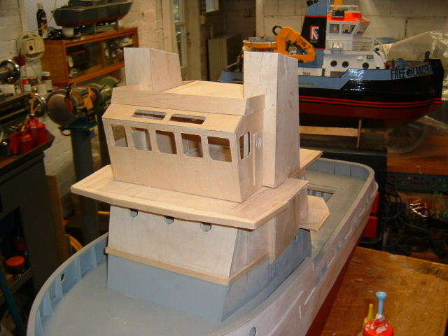
Part - The Sixth
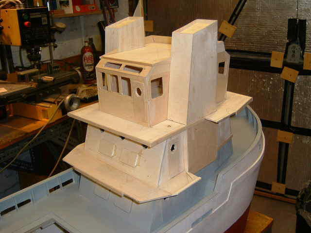
Since part 5 was posted the stays to the propshafts have been added and the paintbrush has been out. With the main parts of the hull completed, bulwarks ( ply )and supports ( from plastic sheet )installed, hull and decks primed and openings for hawse holes cut, attention turns to the superstructure. The boat being larger, though still at 1/24th scale, an additional deck (chartroom) has been incorporated.
The porthole openings and hawse holes were scribed and cut using an 11/32" carpenters drill bit, the thin ply being backed up during this operation by a block of wood to avoid splitting and to assist the screw portion of the bit to draw the tool through the ply. All ply edges to decks are lipped to cover end grain, supports will be added in due course
|
||||||||
|
Part - The Fifth
83 hours and the superstructure is taking shape. I have drawn on details from many boats on the web and am adding ideas as they come to mind. The chartroom and the wheelhouse ( the latter being the next part of the build ) will be removable for access to the ' guts 'of the thing. I have had a lot of advice on Model Boats Forum regarding the size of motors to install....so much that it will be difficult to make up my mind when the time comes!
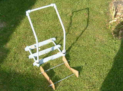
As a ' Bye the way ', having been to the
water today I was able to take a picture of my carrier/launcher, made from
pipe and plumbing fittings there are accessories to enable me to cart and
launch any of my 5, soon to be six, boats. |
||||||||
|
|
||||||||
|
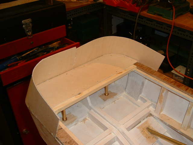
Part - The Forth
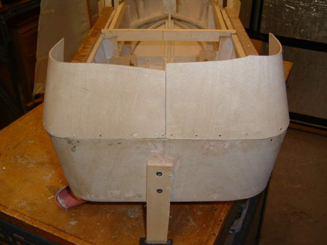
As this project is scratchbuilt and freelance there is a lot of pleasure to be gained from searching the web for interesting detail to be included in the upper decks and bridge. The number of sites dedicated to tugs, service vessels and the like is amazing. Towage companies and ship owners sites have endless information, Too much information in fact and the head reels at the scope, facts and illustrations. Martin Davis's site is a great place to find useful links. Now for the first of the ' Difficult bits ', more difficult that is than persuading the ply sheathing around the bow of the boat, and the stern quarters ! The upper stringer and the edge of the rear deck panel were planed to the correct inclination for the tumblehome, including a transition to vertical at the sides to meet the eventual main run of bulwark. After the raw ply had been offered up, clamped into place and the line of the hull side sheathing marked, the bottom edge of the bulwark was trimmed to line. A trial fit allowed holes to be drilled for the first few pins.
The outer veneer of the ply was dampened and the ply progressively pinned into place.
With the port side fixed the ply was cut on the centreline, ready to match that for the starboard. The joint between hull sheathing and bulwark will eventually be masked by a rubbing strip. The temporary 'Leg' on the stern is to prevent the prop shafts from damage during construction. With the bulwarks placed and fixed they will be rough trimmed pending final trimming once deck panels have been installed and the correct line for the capping can be measured from the deck level. Fifty-one hours into the build it was time to ' Fall-out and wipe swords ' as the Army saying goes. It took a quite considerable physical effort to bend, hold and pin the ply into the correct location! Before the remainder of the bulwarks can be added the decks must be laid. In order that the decks can be laid, the first level of the superstructure has to be installed so that the decks can butt against them. The first level, the upper part of the engine room is to be fixed and the chartroom and bridge deck will be removable, complete with the funnels to provide adequate access to the motors, speed controller, fuse and whatever other electrics I decide to install.
The engine room sides and fore and aft bulkheads are positioned and glued, The joints will be reinforced with glue blocks later, to withstand the rigours of handling . The shape and form of the superstructure are taking shape in my head and have to be reproduced in ply, etc. 3/32" ply will be used from here on up to reduce weight and keep the centre of gravity low.
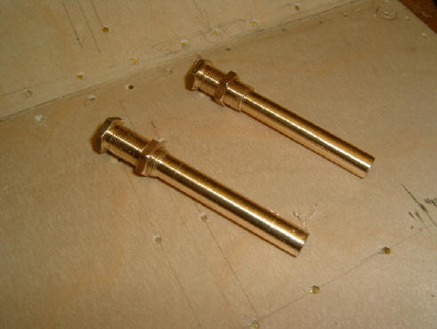
As a break from the joinery, the rudder
tubes and posts have been turned up from P/Bronze and S/Steel. At their
location in the stern and at the position of the prop shaft break through,
blocks have been added to distribute the loads back into the main frame. |
||||||||
|
The rudder tubes are turned from Hex. P/bronze, bored 7/32" for S/steel posts. Expensive materials but off cuts left from the earlier 'Allchin' traction engine build.
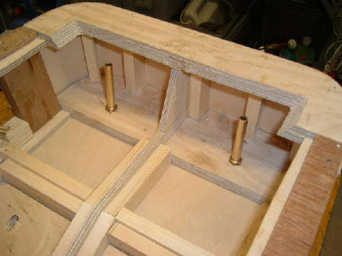
Rudder tubes set temporarily into
place, they will be 'Araldited ' into stern block. For the moment
they are there to check the prop shaft position and inclination.
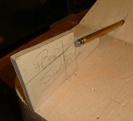
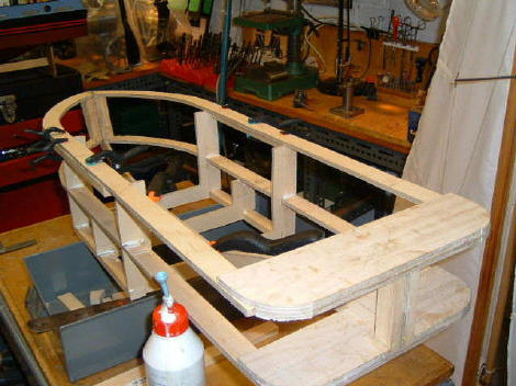
The prop shaft template used to ensure correct inclination, now determines the length of projection to coincide with the centre line of the rudder post and steering nozzle. With the deck laying process complete the bulwarks can be finished and cut to six, the tricky bit is getting the level consistent throughout. Fortunately the 3/32" ply becomes immensely strong when curved to any degree and can be sawn with a tenon saw without damage.
The bulwarks trimmed to the correct height are ready for the supports to be installed, This takes time as very few are similar, specially at the bow and stern At this stage 63 hours into the construction the amount of space in the hold can be assessed. There seems to be plenty of room here for the motor, radio, speed controls etc. Hopefully there will be other equipment too, It is intended to add sound and lights to this version of ' Free lancer '
|
||||||||
|
Part - The Third
|
||||||||
|
|
||||||||
|
Part - The Second
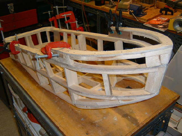
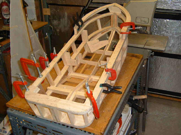
Thank you for including the early picture of the new project Martin. I think viewers must wonder what the boat is going to turn out like from that picture! I use a method of hull construction similar in some ways to the early Aerokit method which used formers and stringers. I have dispensed with the formers. I cut the bulwarks, keel and chines from 1/4" ply (specially purchased this time, not from a skip ) then insert small blocks locally to generate the basic hull form, adding further blocks where the 1/16th ply skin is to be joined. It all looks fairly crude at this stage,
but soon begins to look '
Boatshaped ' ! The benefit to me of this system is that There are no
bulkheads to obstruct the inboard space, allowing freedom of layout for
radio gear and so on.
The hull form is different to Free Lancer............. ' Bigger in the bilges ' one might say. This to improve stability. .................In the case of Free Lancer a considerable amount of lead ( From a skip ) was required along the line of the keel to reduce the heel on tight turns although on test it would recover from 20 degrees or so of heel.. This boat will need less ballast and be more stable,
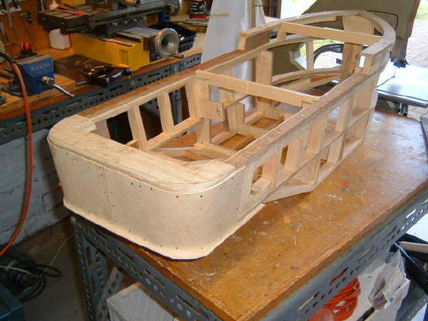
The frames faired off and
the first deck beams installed a start is made on fitting the skin of
1/16" ply. PVA adhesive and brass pins are used ( the PVA, bought by the
gallon...cheaper that way ! ) has proved waterproof after 24 hours
immersion test. It is to be hoped that Free Lancer 2 never suffers
immersion for that length of time . Just a small amount of curvature
ensures that the ply doesn't deflect between supports. The 1/4" overlap is
for careful trimming. |
||||||||
|
Part - The First
|
||||||||
|
|
||||||||
|
Thanks for visiting my build ! |
||||||||
|
Johns
Model Madness |
||||||||