Malcolm Frary |
|||
         |
|||
|
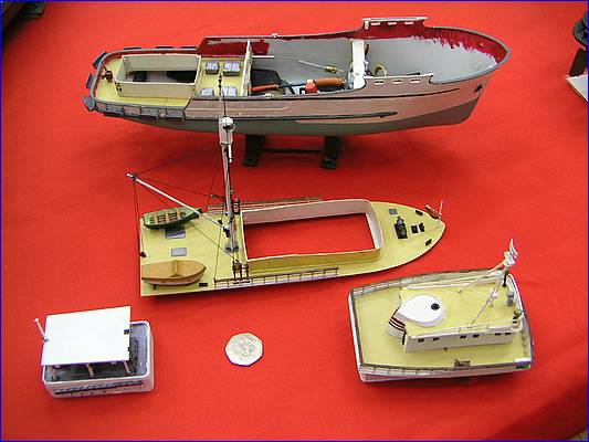
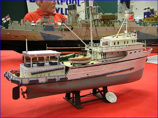
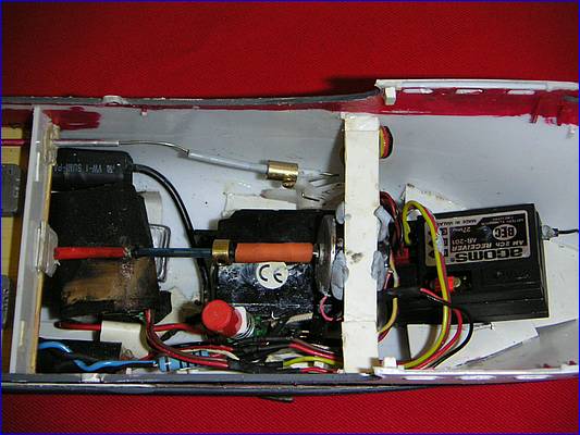
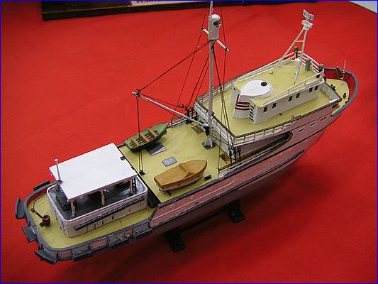
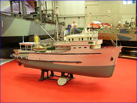
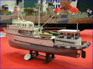
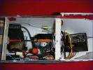
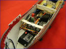
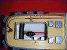
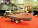
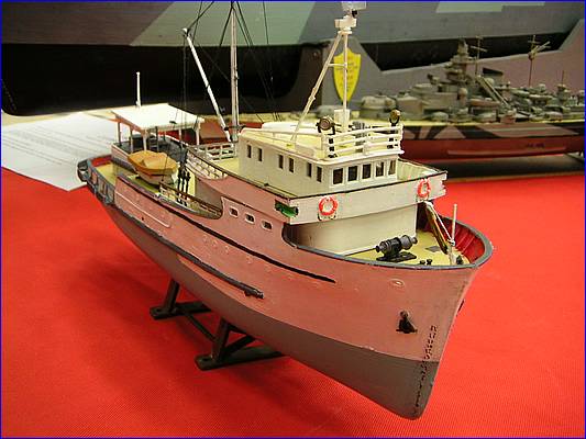
This is another Lindberg conversion of one of their �classic� range, which are still occasionally available. The main aim was to have a small boat with plenty of character at low cost. The �low cost� aim meant NO MINIATURE COMPONENTS! Weighing showed that there was a maximum payload of 12oz. The hull looked like a good stable proposition, which was handy as I wanted to use as much of the supplied detail as possible. My version of weighing consisted of bunging the hull holes (for prop-shaft and rudder fittings) with plasticine, then mounting the hull on a flat surface with a strong light behind it, and the pouring in water until the waterline was reached. This water was then poured into a measuring jug, and the answer read off in fluid ounces. The rest of the kit was then weighed, and, to allow for the weight of the sprues, divided by two, and this subtracted from the hull water. This is a good guide figure for the payload, or the answer to �Will it carry a radio, motor, speed control, batteries, etc��. If you weigh these items and they weigh less than you payload, you shout �Hooray!!� and carry on, if not, you have a re-think. Luckily, this was a �Hooray�, but only just. Next step is to look carefully at all of the bits and try to figure out where the changes will be needed to make it into a working model. I have this belief that it should be possible to change any part without demolishing the model, so access has a high priority. In this case, there is very little freeboard around the after deck, so that needs to be sealed. Fortunately there is the bait house there, so that can be made removable, and mounted over a coaming almost the height of the house itself. On this particular boat, the rudder is very close to the stern. The low freeboard makes a water-tight under-deck tiller difficult, with access impossible, so the tiller arm will go above deck. This also implies running a linkage to connect it above deck. This was to be rendered invisible by painting it bright red - anybody seeing it will automatically assume that it is supposed to be there! So, the after deck was fitted, with its� forward bulkhead, and four freeing ports added at deck level to help drainage. The batteries (5 of AAA) and a charging socket live under here, along with the prop tube and the rudder tube, a piece of drinking straw tube cemented top and bottom. Access via the main deck is for crystal changing (so that I don�t have to be stuck without a sail), and for switching power on and off. This can be done through a hole in the deck under the main superstructure. Most other jobs could be done through this hole, but I decided that it was much easier to be able to remove the entire deck - if there is ever more than a slight splash on that deck, the entire boat is in so much trouble that it would probably have been overwhelmed anyway. The superstructure was also located using a high coaming. All coamings and other bits of extra structure were made from 0.8mm styrene sheet. Past experience has shown that it is a sound idea on this kind of model to cut out as much unnecessary plastic decking as possible. In this case, Lindberg have already done that part of the job. The prop shaft was made from a length of 1.6mm brass wire. The kit prop was used, carefully (and VERY slowly) drilling down through the centre of the boss, and the epoxying the shaft in place. Bearings were cut from Johnsons cotton bud shafts, and the outer tube from a plastic drinking straw (the small diameter, thick-walled type), the bearings being epoxied in place. He coupling used was a rubber tube type, and a thrust bearing made up from a length of cotton bud tube and a brass collar. The motor used was rescued from a dead CD player - an almost perfect replacement for a servo motor, having a longer shaft. The speed control was the electronics from an old servo, with the motor removed and the CD player motor wired in its� place. The dead band is narrow going on for non-existent, but at these prices, who cares? The steering servo is a standard size device, laid on one side under the motor, the ESC living just astern of that. The rudder linkage was made up from lengths of 22g nickel silver wire (point control wire left over in the scrap box from my model railway days), the sections being joined using brass collars and screws from a 5amp mains through connector (6 collars and screws, �1:50). A new rudder was made up from styrene sheet, using the original as a pattern. The receiver was mounted on a shelf in the bow, with the battery pack (5 of AAA NiMH) in a sausage string around the stern. I did put some heat shrink tube on these, but I feel that missing this and using a bit more ballast might have been more useful). The switch, a charging resistor and a small bridge rectifier (saves remembering what polarity the charger has to be) were hung on the wiring loom on the starboard side. Art each stage, a float test was carried out, taking the opportunity to adjust the position of any items, and all was going well until I fitted the mast. The beast came out in its� true colours them, and refused to sit upright. I lowered the C of G a bit by slotting the receiver shelf, and mounting the receiver on a steep slant. Not quite stable yet, but there was still some reserve buoyancy, so I made a 1� oz lead block, and inserted that under the speed control. The boat is now stable in anything but a strong side-wind, when it leans, but then, with all that upstairs and precious little downstairs, this is to be expected. It is a 1 mile walk around the side of the lake where I do most of my sailing, and on a still day it looks good all the way round when accompanying me, and still plenty of life left in the batteries for cruising up and down afterwards. The walk round takes about an hour, which is probably about right for a 1:120 scale fishing boat. Malcolm Faray
|
|||
|
|||
|
Tuna Boats Gytha Lotse Home |
|||